
Silvia Fog Light Rewire

Fog lights are auxiliary lights designed to illuminate the road immediately in front of a vehicle, providing enhanced visibility in adverse weather conditions such as fog, rain, or snow. When wiring fog lights, several methods can be employed, with one common approach being to connect them to the low beam headlights. This method ensures that the fog lights operate in conjunction with the vehicle's low beam headlights, providing a consistent lighting pattern without overwhelming oncoming drivers.
To implement this wiring method, the following components are typically required: fog lights, a relay, wire harnesses, and appropriate connectors. The relay is crucial as it allows the fog lights to draw power directly from the vehicle's battery while being controlled by the low beam circuit. This prevents excessive load on the low beam circuit and ensures reliable operation.
The wiring process begins with the installation of the fog lights, which should be mounted securely to the vehicle's front end. Next, a wire harness is run from the fog lights to the relay, which is positioned near the vehicle's battery for easy access. The relay is then connected to the low beam circuit, typically by tapping into the low beam wire using a splice connector. This connection will activate the relay when the low beams are turned on, allowing current to flow to the fog lights.
It is essential to ensure that all connections are secure and insulated to prevent short circuits. Additionally, the fog lights should be aimed correctly to avoid blinding other drivers while maximizing visibility for the driver. Proper installation and wiring of fog lights not only enhance safety but also comply with legal regulations regarding their use on public roads.I was sitting around trying to decide how to wire my fog lights up. I`ve seen people wire them directly off the low beam or.. 🔗 External reference
Related Circuits
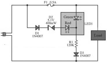
This circuit is designed to monitor the performance of the equipment. It includes a fuse check feature. The circuit is compact and can operate with various power supply voltages. It utilizes a two-color LED, which is of the common...
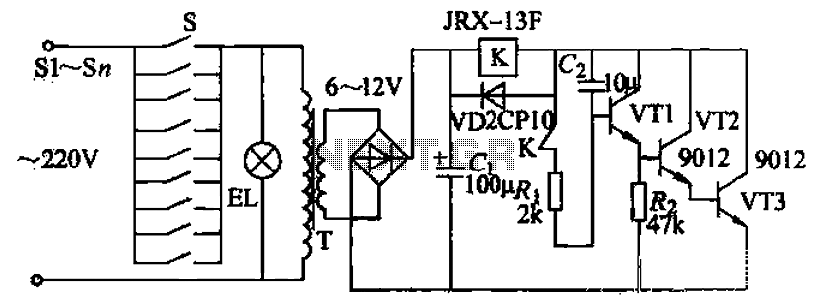
Pressing the button switch Sl-Sn activates the circuit, turning on the transformer T. The low-voltage alternating current from the secondary winding is directed to a bridge rectifier and a filter capacitor Ci, which produces a DC voltage. This voltage...
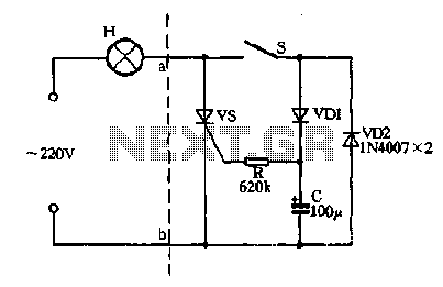
Closing the switch S allows the AC positive half-cycle to flow through diode VDI and resistor R, causing the SCR to open simultaneously at both ends of the capacitor C, which becomes fully charged. During this phase, the positive...
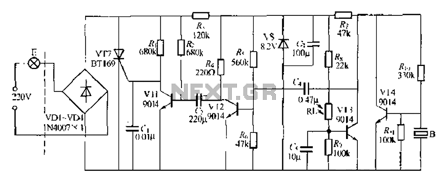
A modified piezoelectric ceramic acoustic-electric transducer is utilized to create a sound and light control system for a stairway walkway with a delay lighting switch. The circuit structure is relatively simple, consisting of diodes VD1 to VD4 and a...
Tired of experimenting with capacitors? It's time to explore supercapacitors, which offer significant storage capabilities. This article provides instructions on building a small LED flashlight utilizing supercapacitors. A minimum voltage of 2 volts is necessary to illuminate the LED,...

Audio light modulations add to the enjoyment of music during functions organised at home or outdoors. Presented here is one such simple circuit in which light is modulated using a small fraction of the audio output from the speaker...