
Homemade Robots polymax improvements
The circuit design for the robot incorporates several critical components that enhance its functionality and performance during competitions. At the core is the ATMEGA644P microcontroller, which handles all processing tasks, including motor control, sensor data acquisition, and decision-making algorithms. The microcontroller's increased memory capacity allows for more complex programming and the implementation of advanced features.
The motor control section utilizes LMD18200T chips, which are configured in a H-bridge arrangement to drive the motors efficiently. The low on-resistance of these MOSFETs minimizes power loss, ensuring that the motors receive nearly the full voltage from the battery pack, thereby maximizing speed and minimizing heat generation. The power supply circuit is designed to accommodate the increased voltage from the battery pack, ensuring stable operation of all components.
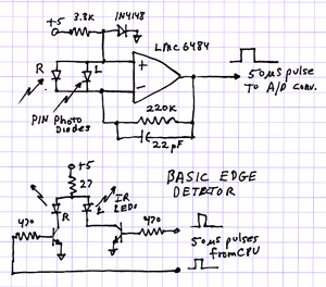
For line detection, the circuit includes nine LEDs and corresponding photodetectors. This arrangement allows for more accurate detection of the line's position, as the additional LED fills in the gaps that previously caused issues when the line was not directly under a photocell. The output from the photodetectors is fed into the microcontroller, which processes the signals to determine the robot's position relative to the line.
The beacon tracking system is enhanced by the addition of shielding around the photocells, which reduces interference from ambient light. This feature is crucial for maintaining reliable operation in varying lighting conditions. The software algorithms governing the beacon tracking have been refined to improve robustness, ensuring that the robot can effectively navigate towards the beacon even in challenging environments.
Object detection is facilitated by six IR LEDs and PIN photodiodes, which work together to identify obstacles in the robot's path. This system is critical for competitions that require precise navigation and obstacle avoidance.
Overall, the comprehensive design and implementation of these circuits and systems contribute significantly to the robot's performance in competitive scenarios, allowing for improved speed, accuracy, and reliability.The 2009 Robot Rally spotlighted all the flaws that result from a quick 3 week engineering and building project. Time saving shortcuts in code and hardware bit my butt several times. Failed edge detectors - Ouch! Failed beacon tracker. chomp! Ow! Line follower reversal - Arrrg! I`m happy to report I`ve investigated all the issues that cropped up and fixed them all. The bot still isn`t perfect but it`s a whole lot better than before. I`ve also cleaned up the software code and documented it better. Here`s what has been changed and fixed. Source code and schematics may be downloaded from links at the bottom of this page. The Atmel AVR ATMEGA8535P was full. I used all 8192 bytes of program space. There was no room left for enhancements or bug fixes. So, I ordered some ATMEGA644P chips from DigiKey. Only Five bucks each, such a deal! These are hardware pin compatible with the old 8535 so no hardware changes were needed. They have 64K program memory and 4k RAM. This is 8 times the memory of the old CPU. They are mostly software compatible too. Yeah, "mostly". That means spending a lot of time going over the code and finding the differences in the names and bit functions of all the internal configuration registers. Also, the avr-gcc open source compiler and avrdude program downloader I had didn`t support the 644 so I had to hunt down the latest version for the Mac.
I downloaded and installed AVR Crosspack. Several days were spent hunting down bugs caused by the CPU upgrade. L293D h-bridge chips suck. They have nearly 2 volts of drop across them and run hot as hell. I was using two in parallel for each motor and they still ran very hot. Due the voltage drop the motors only got 10 volts out of 12 that was available. This means that top speed is reduced by about 20%. So, I removed them and mounted a pair of LMD18200T chips on the aluminum chassis. These are MOSFET based chips and have 0. 3 ohm resistance. The motors can receive almost full battery voltage. Robot speed increased considerably. Hear that 3pi bot guys Lower voltage drop and chassis heatsinking means no more smoking hot h-bridges. More Power! I still needed more speed to have a chance against the 3pi robots in line following. I crammed two more cells in the battery pack for a total of 14. 4 volts. The motors are now 2x over volted. Yet, they hardly get warm. And, yes, the bot still tracks the line at full speed! Now we have a chance of beating the 3pi in basic line following. Originally I had 8 red LEDs aligned with 8 photocells to track the line. They were spaced 0. 7 inches apart. The line we need to follow is 0. 75 inches wide. When the line was between photocells it would sometimes "dissappear" and the bot would think there was no line present.
For basic line following this wasn`t a problem. Small side to side movements self corrected the situation. However, the maze contest required taking action when T intersections and dead ends are found. The bot needs to know for certain if it`s on a line or not. This problem was fixed by using 9 LEDS and putting them between the photocells. The blind spots are filled in and the line present and centroid code is much happier now. Since I had problems with stray room lighting in the beacon killer contest I decided to add some shielding to the beacon sensor photocells. The slot covers 120 degrees and is 3/16 inch wide. I machined it from a piece of round PVC stock on a lathe and mill. Major changes in software were still required to make the beacon tracker "bullet proof". More about that later. Also shown in the photo on the left are the 6 IR LEDs for object detection and the pair of PIN photdiodes above them.
They worked great and didn`t need any changes. The bulldozer contest involves driving around on a surface 4 inches off the floor while pushing objects off without driving yourself off. Originally I used an off-the-shelf reflective IR sensor consisting of a phototran 🔗 External reference
Related Circuits
Voicemail capability (though not implemented) utilizes four ADCs that can sample and record phone audio. A storage volume (SD card) needs to be connected. This project is inspired by other homemade exchanges: Markus Wandel and Andrew Holme. The project...
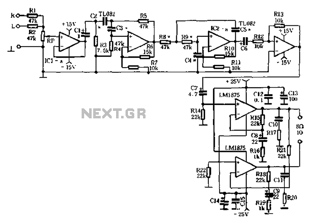
Audio equipment utilizes the left and right channel signal from the former speaker output terminals. The Rl and RZ mixed units are processed through a buffer (IC1a) before passing through a high and low pass filter. The filter employs...
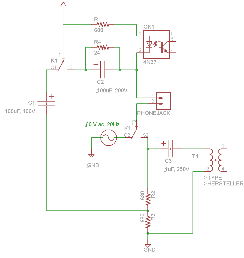
Instructions for constructing a 1kW synchronous rotary spark gap (SRSG) Tesla Coil. This device operates using mains power and is powered by a 1kVA (10mA, 10kV) neon sign transformer (NST). The construction of a 1kW synchronous rotary spark gap Tesla...
The simplest solution for implementing joystick control for a robot is to program the actions in software on a microcontroller. However, many users prefer off-the-shelf components, thus this circuit is designed using diodes, resistors, transistors, and a FAN8200 motor...
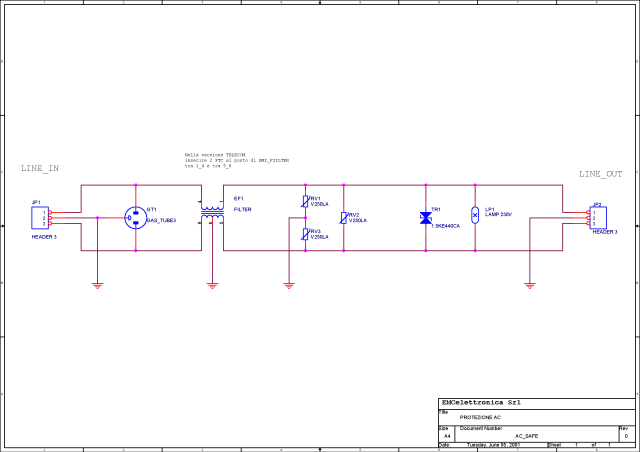
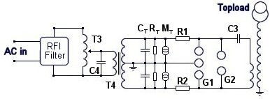
What is a circuit breaker? When is an AC power line filter or a phone line filter necessary? How can a noise filter be designed? Is it possible to create a homemade surge protector? The following circuit protection options...
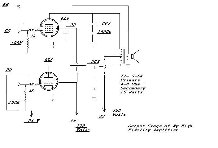
An amplifier designed to complement an antique Meissner AM High Fidelity tuner that has been restored. Upon completion, the amplifier delivered such impressive sound quality that it became the preferred choice for listening to CDs while working. The only...