
Light to Frequency converter
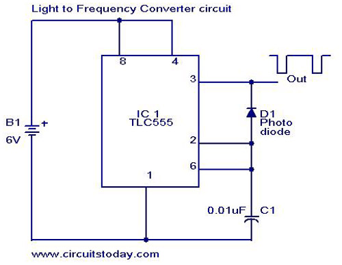
The light-to-frequency converter circuit is designed to convert varying light intensities into corresponding frequency signals, facilitating the measurement of light levels. The circuit employs the TLC555 timer IC, which operates in an astable mode to generate a square wave output whose frequency is proportional to the input light intensity.
The primary components of the circuit include the TLC555 timer IC, a photodetector (such as a photodiode or phototransistor), resistors, and capacitors. The photodetector captures the incoming light and produces a current proportional to the light intensity. This current is fed into the TLC555, which is configured to convert the current signal into a frequency output.
In the astable mode of operation, the TLC555 continuously switches between its high and low states, producing a square wave. The frequency of this output is determined by the values of the timing resistors and capacitor connected to the IC. The relationship between the light intensity and the output frequency can be adjusted by selecting appropriate resistor and capacitor values, allowing for calibration based on specific measurement requirements.
The schematic diagram typically shows the TLC555 connected with the photodetector and timing components. It is essential to ensure proper connections and component values for accurate light intensity measurement. This circuit can be applied in various applications, including ambient light sensing, automatic lighting systems, and scientific experiments that require precise light intensity monitoring.A simple light to frequency converter circuit with diagram and schematic.Used as Light intensity measurement circuit.Design using TLC555, a cmos version of NE 555 timer IC.. 🔗 External reference
Related Circuits
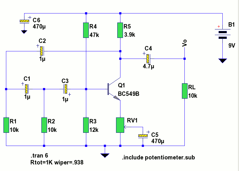
A low-frequency test oscillator designed for testing tone controls and conducting experiments. The low-frequency test oscillator serves as a versatile tool in audio engineering, particularly for evaluating tone control circuits and facilitating various audio experiments. This device generates sinusoidal waveforms...
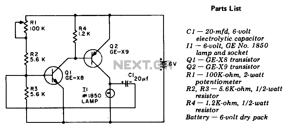
The circuit is a two-stage, direct-coupled transistor amplifier configured as a free-running multivibrator. Both the flash duration and flash interval can be adjusted by turning the potentiometer, R1. The described circuit operates as a two-stage, direct-coupled transistor amplifier, functioning as...
This inverter circuit can provide up to 800mA of 12V power from a 6V supply. For example, you could run 12V car accessories in a 6V (British?) car. The circuit is simple, about 75% efficient and quite useful. By...
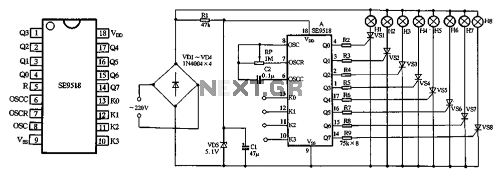
The circuit utilizes a 220V AC input, which is processed through a VD1-VD4 bridge rectifier to convert the AC voltage into a DC voltage. This DC voltage is then used to power eight lights labeled H1 to H8. Additionally,...
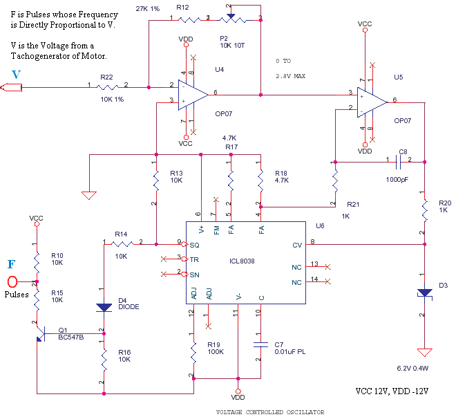
This is a small circuit designed to drive an impact counter, with the central component being the ICL8038. The circuit is intended for use with a motor that drives a conveyor, which includes a feedback mechanism known as a...
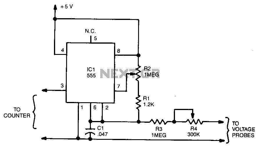
The output frequency from IC pin 3 is determined by the voltage input to pin 6. A standard frequency counter can be used to measure voltages directly over a limited range from 0 to 5 V. In this circuit,...