
Lights-On Warning

The circuit operates using a 555 timer configured in monostable mode, where the timer generates a single output pulse in response to a trigger. The power source is derived from the vehicle's side lights, which ensures that the circuit remains inactive when the lights are off, thereby conserving battery power and preventing unnecessary alarm activation. The 555 timer's reset pin is crucial for controlling the timer's operation; it is connected to the emitter of transistor Q1, which acts as a switch.
When the ignition is turned on, the auxiliary terminal supplies voltage to the base of Q1 through resistor R1. This base current allows Q1 to enter saturation, effectively grounding pin 4 of the 555 timer. In this state, the timer's output remains low, and the alarm is disabled. The use of a resistor to limit the base current is essential for protecting the transistor from excessive current, which could lead to component failure.
If the ignition is turned off while the side lights are still illuminated, the power continues to flow to the 555 timer, as it is connected to the side lights. This condition results in Q1 turning off, releasing the reset pin of the timer and allowing it to oscillate. The output from the timer then activates the alarm, alerting the user.
The optional switch S1 provides a manual override feature, allowing the user to bypass the automatic control of the alarm system. This can be useful in situations where the alarm needs to be silenced without turning off the ignition or lights. The design ensures that the alarm system is both responsive and user-friendly, offering flexibility in operation while maintaining safety and efficiency in the vehicle's electrical system. Because power for the circuit is obtained from the car"s side lights, the circuit can"t oscillate unless the lights are o n. The reset pin on the 555 connects to transistor Ql. The base of Ql is connected through R1 to the ignition auxiliary terminal on the car"s fuse box. When the ignition is turned on, power is supplied to the base of Ql, which turns it on. With Ql turned on, pin 4 of Ul is tied low, which disables the oscillator and inhibits the alarm. If the ignition is turned off while the lights are on, power is applied to the 555 and Ql is turned off, and the alarm starts. Switch Si is an optional override.
Related Circuits

This circuit is designed as a warning flasher to alert road users to dangerous situations in low-light conditions. It can also function as a bicycle light, subject to applicable traffic regulations. White LEDs are recommended for use as a...
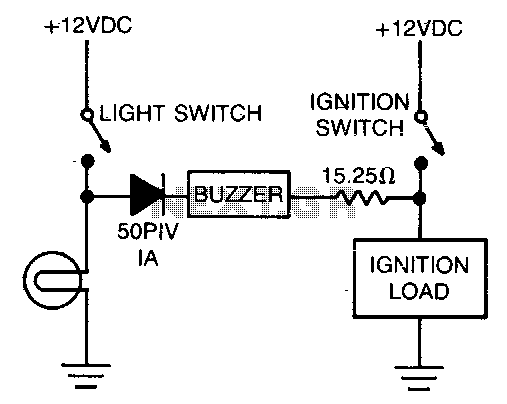
The alarm consists of a diode, buzzer, and a limiting resistor. The diode functions as a switch that enables the buzzer to activate only when the light switch is closed and the ignition is turned off. The circuit described utilizes...
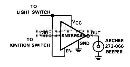
The SN75604, which features input control logic and requires only a single supply rail, can be utilized in light activation sensors and alarm drivers. The device's Vqq and enable inputs are connected to a voltage lead from the light...
This circuit will light a lamp at a remote location when the doorbell switch is pressed. This circuit should only be used with the solenoid type doorbells; the electronic type that play tunes will not work here. It is...

The circuit functions as a danger zone warning system incorporating a regulator circuit, a pyroelectric infrared detection trigger circuit, an electronic switching circuit, and audio circuits. The regulator circuit includes a three-terminal regulator integrated circuit (IC2), a resistor (R3),...

This circuit utilizes battery-powered blinking warning lights for roadblocks. It can operate on AC power to create barricades with warning indicators. The circuit incorporates an NE555 timer and resistors RP1 and RP2, along with resistor R1, to form a...