
DC capacitor tester circuit diagram composed of 555
The DC capacitor tester circuit employs a 555 timer IC in astable mode to generate a square wave pulse. The frequency of this pulse is inversely related to the capacitance of the capacitor being tested. The capacitor under test is connected in parallel with a resistor, forming an RC time constant that determines the charging and discharging rate of the capacitor.
When the capacitor charges through the resistor, the voltage across the capacitor reaches a threshold that triggers the 555 timer to switch states, resulting in a pulse output. This pulse is then processed by a one-shot circuit, which generates a single output pulse of a fixed duration each time the input pulse is detected. This pulse width is directly proportional to the capacitance value.
The DC amplifier is used to amplify the output signal from the one-shot circuit to a level suitable for driving a meter indication circuit, which displays the measured capacitance. The meter can be an analog or digital type, depending on the design requirements. The segmented ranges allow the tester to provide accurate measurements across a wide spectrum of capacitor values, making it a versatile tool for electronic testing and troubleshooting.
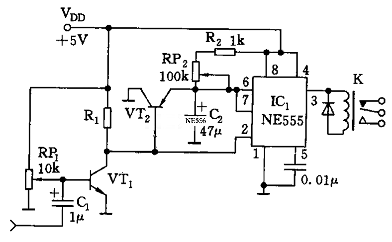
This circuit is particularly useful in the field of electronics for evaluating capacitor health and performance, ensuring that components meet specified tolerances before being incorporated into larger circuits. Proper calibration and component selection are essential for achieving precise measurements and reliable operation of the capacitor tester.DC capacitor tester circuit diagram composed of 555 is shown as the chart. The tester is composed of the pulse generator, one-shot, DC amplifier and meter indication circuit. It can measures the npF ~ 10?F capacitor. The range is divided into 0 ~ 100PF, 0 ~ 1nF, 0 ~ 10nF, 0 ~ 100nF, 0 ~ 1?F, 0 ~ 10?F.. 🔗 External reference
Related Circuits
Although it may lack the aesthetic appeal of traditional mercury barometers, which feature long glass tubes mounted on intricately carved and polished wood, the Torricelli barometer being discussed serves as a functional equivalent and electronic replica of the classic...
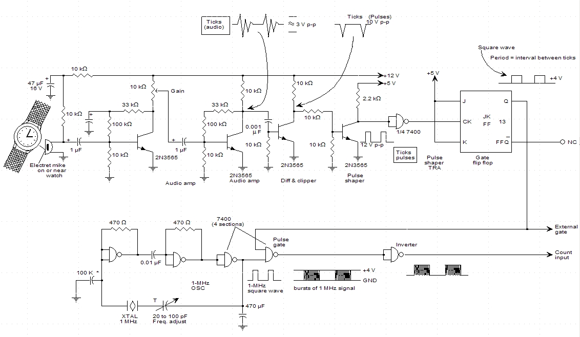
A schematic for a watch timer was found in a hobby electronics book. The circuit adapts a frequency counter to measure intervals. Watch ticks are clipped, shaped, and formed into a square wave. This square wave is utilized to...
This design is for a thermometer circuit that utilizes the LM35 integrated circuit (IC) as a temperature sensor. It is a straightforward circuit that allows for the measurement of room temperature using a digital voltmeter or any voltmeter capable...
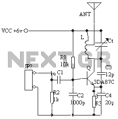
The ordinary triode 3DA87C is utilized to create a long-range FM transmitter circuit, which functions as a standard three-point oscillator circuit. This remote transmitter circuit is capable of large current emissions, achieving a range of up to 1 kilometer...
These accessories are low-cost, high-speed, bifet-input operational amplifiers utilizing internally compensated voltage (BI-FET II technology). They require low supply voltages while offering a wide gain bandwidth product and fast slew rate. Additionally, well-matched high voltage JFET input devices accommodate...
The timing circuit utilizes the 556 dual time base circuit, which includes an intermediate access N8281 crossover network. This design does not require a large volume capacitor, allowing for extended time delays. Initially, the first half of the 556...
Warning: include(partials/cookie-banner.php): Failed to open stream: Permission denied in /var/www/html/nextgr/view-circuit.php on line 713
Warning: include(): Failed opening 'partials/cookie-banner.php' for inclusion (include_path='.:/usr/share/php') in /var/www/html/nextgr/view-circuit.php on line 713