
Improved differential circuit diagram

The circuit modification involves integrating the differential circuit with an integrator component, which plays a crucial role in signal processing applications. The integrator is designed to output a voltage that is proportional to the integral of the input signal over time. This is particularly useful in applications where the cumulative effect of a signal is required, such as in analog computing or control systems.
In Figure A1, the integrator is typically implemented using an operational amplifier (op-amp) configured in an inverting mode. The input signal is applied to the inverting terminal of the op-amp through a resistor, while a capacitor is connected between the output and the inverting terminal, forming a feedback loop. The non-inverting terminal is grounded.
The output voltage of the integrator can be expressed mathematically as V_out(t) = -(1/RC) ∫ V_in(t) dt, where R is the resistance, C is the capacitance, and V_in(t) is the input voltage. This equation indicates that the output voltage is the negative integral of the input voltage, scaled by the time constant RC of the circuit.
Additionally, it is essential to consider the frequency response of the integrator, as it can significantly influence the performance of the overall differential circuit. The integrator will have a high gain at low frequencies and will attenuate high-frequency signals, which can lead to phase shifts and potential instability in certain applications. Therefore, proper selection of the resistor and capacitor values is critical to ensure that the integrator operates effectively within the desired frequency range.
Overall, the integration of the differential circuit with an integrator enhances its functionality, enabling it to process signals that require accumulation over time, thereby expanding the potential applications in various electronic systems. As shown for the modification of the differential circuit. Figure, A1 is an integrator, the output is
Related Circuits
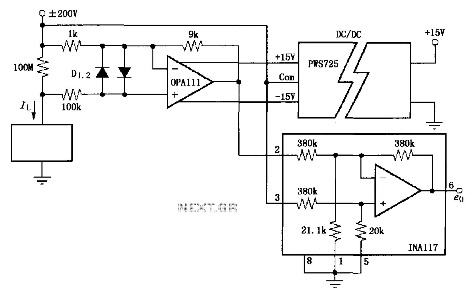
The circuit illustrated in FIG OPA111 is designed for measuring input buffer leakage current. The transistors D1 and D2, which are 2N3904 types, short the base and collector contacts while leaving the emitter open. When a power supply of...

The circuit expands a single 15-pin D-sub VGA output to multiple outputs, allowing for the connection of up to six monitors simultaneously. The input VGA connector is positioned on the left side, while the six output VGA connectors are...

The preamplifier circuit is designed to offer appropriate loading for phono cartridges with reluctance. It achieves a gain of approximately 25 dB at 1 kHz (converting an input of 2.2 mV to an output of 100 mV). The circuit...
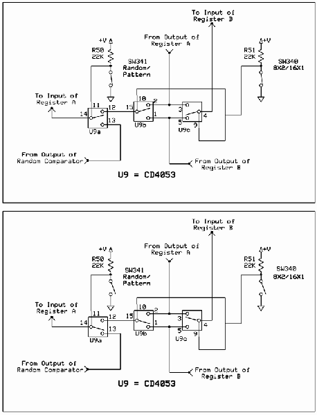
The circuit involves Clock and Load functions, with the Load function being described first. The component U5, a CD4013, is responsible for executing the load function by determining whether the shift register integrated circuits (ICs) operate in parallel or...
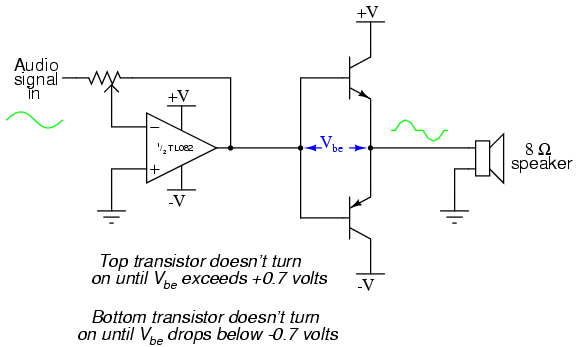
This project is an audio amplifier designed to amplify output signals from small radios, tape players, CD players, or other audio signal sources. For stereo operation, two identical amplifiers must be constructed—one for the left channel and another for...
Using an old moving coil instrument, it is easy to create a simple voltmeter that indicates the status of a telephone line at a glance. The circuit's high input impedance allows it to be permanently connected to the line,...