
Line Follower Robot
The schematic for a Line Follower Robot using analog components typically includes the following key elements:
1. **Photocell Sensor and LED**: The CdS photocell sensor is connected in a voltage divider configuration with a resistor. The LED is placed to illuminate the area being sensed, enhancing the contrast between the black track and the white surface.
2. **Operational Amplifier**: An operational amplifier is used to amplify the voltage signal from the photocell. The output of the op-amp is then fed into a comparator circuit that determines the light intensity level.
3. **Motor Driver Circuit**: The outputs from the comparator can control a H-bridge motor driver circuit. The motor driver controls the direction and speed of the DC motors based on the PWM signal generated from the op-amp output.
4. **PWM Generation**: The PWM signal can be generated using a 555 timer IC configured in astable mode. The duty cycle of the PWM signal can be modulated based on the op-amp output, which corresponds to the light intensity detected by the photocell.
5. **DC Motors**: Two DC motors are used for movement, with their speeds controlled by the PWM signals. The motors are connected to the H-bridge, allowing for bidirectional control.
6. **Power Supply**: A suitable power supply is required to power the motors and the control circuitry. Voltage regulators may be employed to ensure that the op-amp and other components receive the appropriate voltage levels.
The overall design aims to achieve responsive and smooth navigation along the track, minimizing zigzag movements through proportional speed adjustments based on sensor feedback. Proper calibration and tuning of the components will enhance the performance of the LFR, making it an effective educational project for beginners in robotics and electronics.Designing a simple and yet functional Line Follower Robot (LFR) is always a fascinating and challenging subject to be learned, the LFR actually could be implemented in many ways start from a simple two transistors to a sophisticated PID (Proportional, Integrate and Differential) which take advantage of the programmable feature of microcontroller t o calculate the PID equation to successfully navigate the black track line on a white background surface. Designing a non microcontroller based LFR is quite challenging tasks as we need to limit the electronic components numbers so the LFR will not too complicated to be built by most average robotics beginners or electronic hobbyists, but at the same time we need to have a good speed control mechanism in order for the LFR to navigate the black track line successfully.
The microcontroller based design LFR in the other hand is a popular choice because it reduces a number of electronic components significantly while still providing a flexible programmable control to the LFR. On this tutorial we are going to build yet another LFR using just the standard analog components easily found on the market but use the same speed control method technique found in many good microcontroller based Line Follower Robot design.
As the result we could get a good precision analog line follower robot that comparable to the microcontroller based Line Follower Robot design. On this tutorial you will also learn many useful information of how to use the operational amplifier.
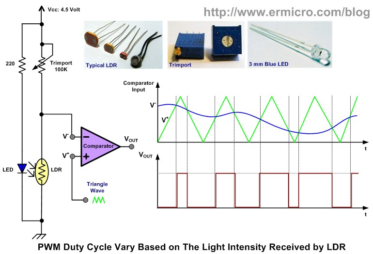
This Line Follower Robot basically use a Cadmium Sulphide (CdS) photocell sensor or known as Light Dependent Resistor (LDR) and the high intensity blue Light Emitting Diode (LED) to illuminate the area under the photocell sensor to sense the black track line and the DC motor speed control technique to navigate the black line track as shown on this following picture: The easy method to navigate the black track line is to turn ON and OFF the left or the right DC motor according to the sensor reading (black turn OFF and white turn ON), but using this method will make the LFR to move in zigzag way. By proportionally control both left and right DC motor speed according to the light intensity level received by the photocell sensor (reflected back by the black track line) we could make the LFR easily navigate this track.
The common technique to control the motor speed efficiently is to use a pulse signal known as the pulse width modulation or PWM for short. PWM basically is an ON and OFF pulse signal with a constant period or frequency. The proportion of pulse ON time to the pulse period is called a duty cycle and it expressed in percentage.
For example if the proportion of pulse ON time is 50% to the total pulse period than we say that the PWM duty cycle is 50%. The PWM duty cycle percentage is corresponding to the average power produced by the pulse signal; the lower percentage produces less power than the higher percentage.
Therefore by changing the PWM duty cycles we could change the average voltage across the DC motor terminals, this mean we could vary the DC motor speed just by changing the PWM duty cycle. Therefore to make the LFR smoothly navigate the black track line, we have to adjust the PWM duty cycle according to the photocell sensor reading.
The brighter light intensity level received by sensor (sensor is on the white surface) will result in higher PWM duty cycle percentage and the darker light intensity level (sensor is on the black line) received by photocell sensor will result in lower PWM duty cycle percentage. By converting each of the photocell sensor light intensity level reading to the corresponding voltage level we could achieve this objective by using what is known as the Voltage Control Pulse Width Modulation principal.
Actually generating the PWM signal is easier with microcontroller instead of discrete components because all you have to do is to program t 🔗 External reference
Related Circuits
The 567 IC tone decoder/detector can be utilized to construct a remote control or intercom system. This circuit is capable of controlling a relay or transmitting an audio signal. The 567 IC is a versatile component often employed in tone...
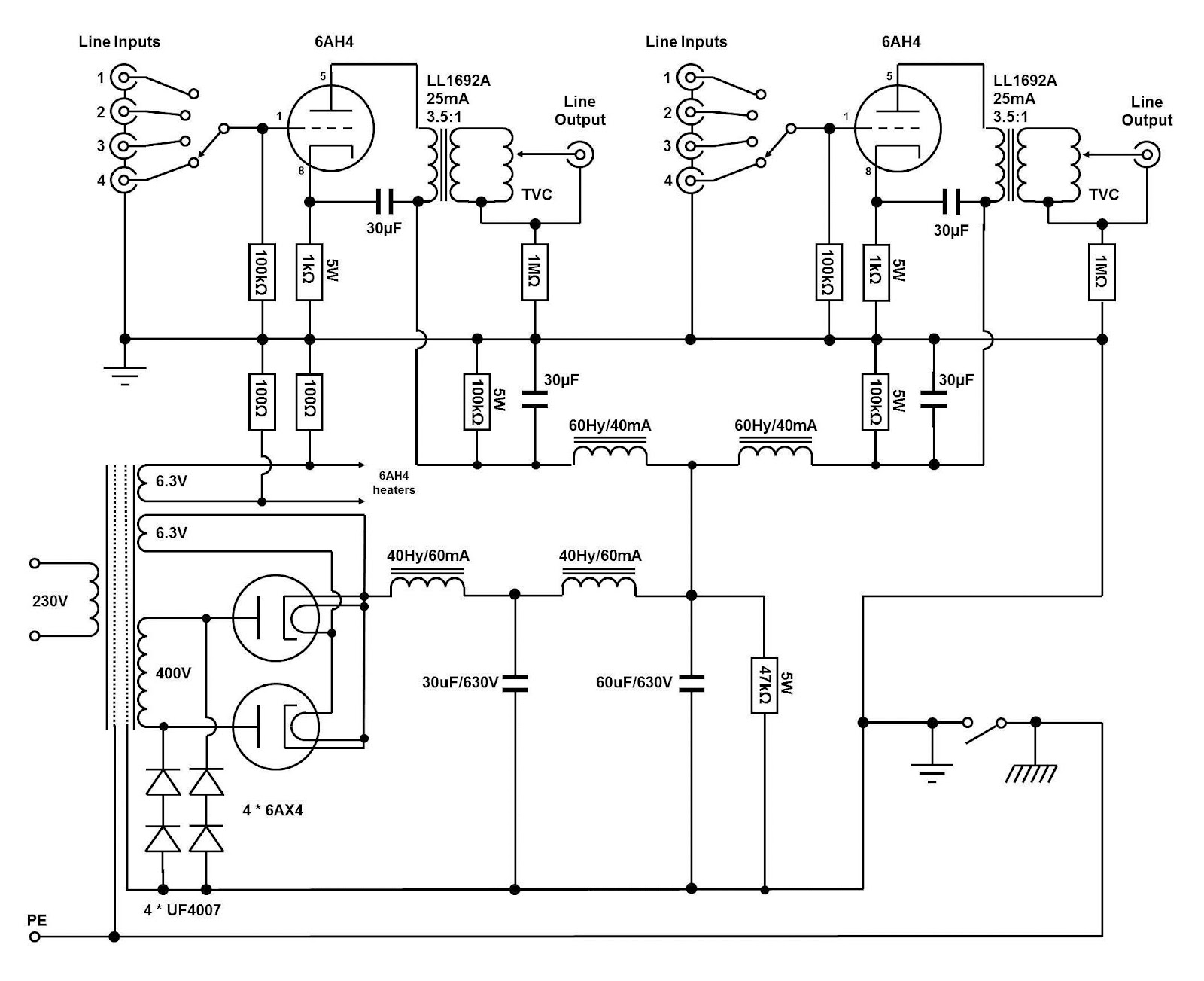
The circuit and assembly process of the line stage is presented in two separate articles. This linestage shares the same circuit as the two chassis version previously described. However, in this design, the power supply and preamplifier are housed...
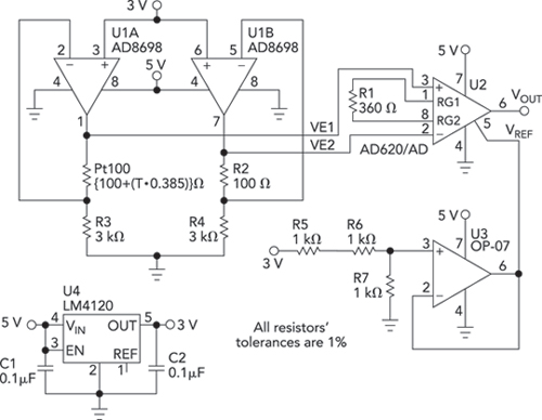
Bridge circuits are widely used for conditioning signals from resistive sensors. These circuits are sensitive to minor changes in resistance, providing a differential output from a single current or voltage source. However, the sensors connected to a passive bridge...
The device employs a microammeter with a full-scale deflection of 50 µA and a resistance of 2 kilohms. The upper limit of the voltmeter's measuring range is 1 V, and within the range of 0.2 to 1 V, the...
A modification is being planned for a Genesis console to enable S-Video and RCA jack outputs. Current modifications typically utilize the headphone jack as the source for stereo sound. However, there is a preference to bypass the volume control...
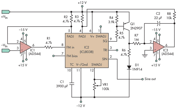
This basic voltage-controlled oscillator (VCO) and waveform generator integrated circuit (IC) circuit features a voltage follower loop (formed with IC1) and a symmetry feedback loop (IC3) designed to eliminate asymmetric duty cycles that can lead to distortion at low...