
VOLTMETER WITH IMPROVED LINEARITY CIRCUIT DIAGRAM
The voltmeter circuit is designed to utilize a microammeter to measure voltage levels accurately within specified ranges while minimizing errors associated with nonlinearity. The microammeter, with its low full-scale deflection current, allows for precise measurements, particularly in sensitive applications. The selection of resistors R1, R2, and R3 is critical for calibration, ensuring that the measurements remain within acceptable error margins across the operational range.
The rectification process is achieved through the use of p-n-p transistors, which are configured to form a full-wave rectifier. This configuration allows for effective conversion of alternating current (AC) signals to direct current (DC), which is necessary for the microammeter to display voltage readings accurately. The choice of silicon transistors for higher voltage ranges enhances the circuit's reliability and performance, as they provide better thermal stability and lower leakage currents compared to other types of transistors.
The input impedance is an important parameter, as it affects the voltmeter's interaction with the source being measured. A higher input impedance ensures that the voltmeter does not significantly load the circuit under test, thereby maintaining the integrity of the measurement. The design also allows for the incorporation of an additional voltage divider to expand the measurement range, although care must be taken to avoid compromising linearity through the introduction of additional calibration resistors.
Overall, this voltmeter design is a robust solution for precise voltage measurement, with careful consideration given to component selection, calibration, and circuit configuration to achieve optimal performance across various measurement scenarios.The device uses a microammeter with full scale deflection of 50 uA and with the resistance of 2 kilohms. The upper limit of the measuring range of the voltmeter is 1 V, and in the range of 0. 2. 1 V the measurement error due to the nonlinearity of the scale is less than 1% of the full scale range.
By selection of the resistor R3 values the voltmeter is calibrated at the middle of the scale, and by selection of the resistor R1 values - in the end of the scale. The linearization of the right side of the scale achieved due to the base current, which creates a voltage drop across the resistor R2.
Because of this the gain of the rectifier are reduced to the end of the scale as required. If the measurement range is 3. 5 Volts and above, then it is better to use a silicon transistor in the rectifier. This voltmeter for the range of 10 V with the transistor KT3102D, has an error due to the nonlinearity of the scale at range of 1 V about 2%, and in the range of 2. 10 V - less than 0. 1% of the full scale range. Parameters of the circuit components are: R1 - 20 kilohm, R2 - 180 kilohms, and R3 - 62 kilohms. A voltmeter with a full-wave rectifier can be implemented with transistors of the same p-n-p type as shown in Fig.
2. The resistance of the resistors R4, R6 is roughly determined from the relation: R
The use of additional resistors shifting the balance achieved in the calibration, and the linearity of the scale gets worse. 🔗 External reference
Related Circuits
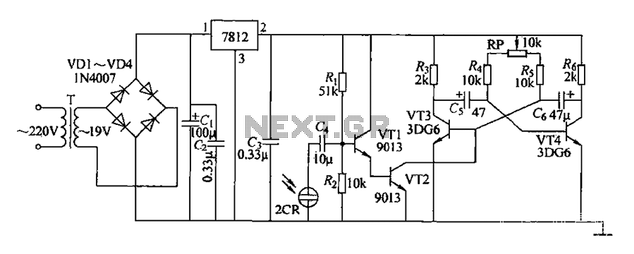
220V AC voltage is transformed by transformer T to 19V. After passing through a full-wave bridge rectifier and filter capacitor C, the voltage is regulated to DC using a 7812 voltage regulator. When the battery indicator light is illuminated,...
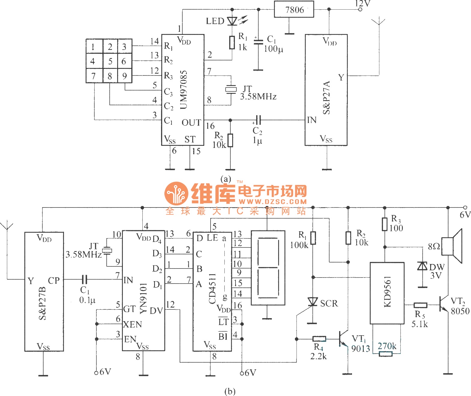
It utilizes a DTMF encoder output, which generates a dual-tone multi-frequency coded signal to modulate the transmitted carrier frequency. This configuration allows for the formation of a DTMF-encoded radio paging system. The circuit incorporates a DTMF encoding chip, UM97085,...
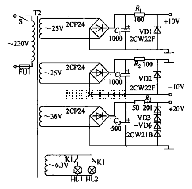
DC power supply with a shunt, rectifier, filter, limiter, and regulator. The circuit is simple and cost-effective, capable of meeting the requirements. The 6.3V indicator lights HL1 and HL2 indicate the lathe's running and stopping status through a relay...
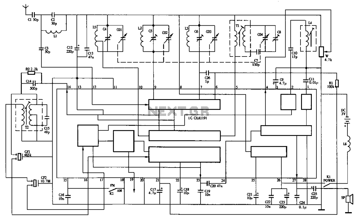
The circuit diagram of the Desheng R-202T type two-band radio is as follows. The Desheng R-202T is a two-band radio receiver designed to operate on both AM and FM frequencies. The circuit typically includes several key components that facilitate the...

The Door Buzzer circuit utilizes an IC 555 to generate a sound resembling an electric bell. When the switch S1 is pressed, a loud sound is produced. This circuit is designed to be simple and requires minimal components. It...
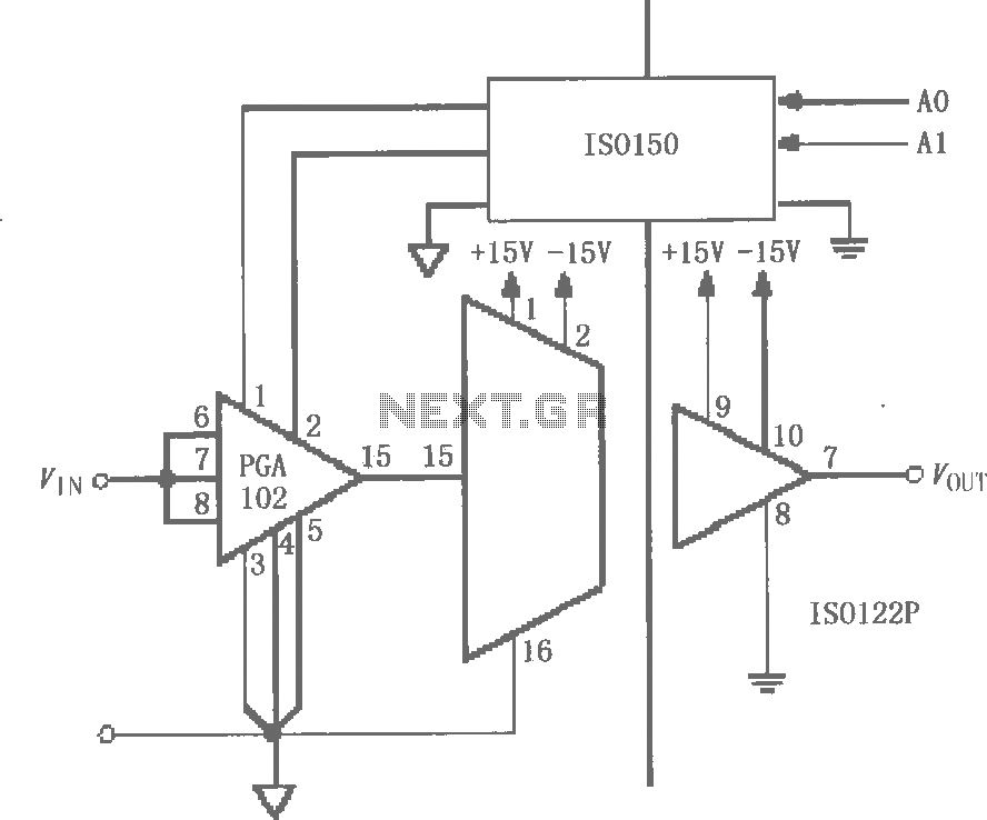
The circuit features grounds ISO122/124 and PGA102, with ISO150 forming a gain programmable channel isolation circuit. The input signal VIN is amplified by the instrumentation amplifier PGA102 to ISO122P, which then outputs VOUT from the isolation amplifier ISO102P. Two...