
Linearize measurements from bridge circuits
Bridge circuits are essential for accurately conditioning signals from resistive sensors, particularly in applications involving temperature measurement. The active bridge circuit described utilizes the Pt100 RTD, which is favored for its precise temperature response. The configuration of resistors R3 and R4 ensures that the bridge operates effectively at a constant current, thus maintaining balance and providing a stable output voltage proportional to temperature changes.
In practical applications, the linearization of the output is critical for ensuring that the readings from the RTD correspond accurately to temperature changes. The circuit's design allows for a unipolar power supply, simplifying power requirements and enhancing portability in various sensor applications. The inclusion of linearizing circuits or software-based linearization becomes necessary when dealing with passive bridges that exhibit non-linear characteristics.
The careful selection of the excitation current is also crucial. The circuit's ability to provide 1 mA of excitation current ensures that the Pt100 RTD operates within its optimal range, thereby delivering reliable performance. Low power dissipation is a significant advantage, as it reduces the risk of self-heating effects that could lead to erroneous readings. This design consideration is especially important in precision measurement applications where accuracy is paramount.
Overall, the described active bridge circuit exemplifies a robust solution for interfacing resistive temperature sensors, ensuring linear output while minimizing power consumption and maintaining measurement integrity across a specified temperature range.Bridge circuits have long been popular for conditioning signals from resistive sensors. These circuits are sensitive to small changes in resistance, and they provide a differential output from a single current or voltage source. But the sensors you connect to a passive bridge with one measuring branch don`t produce linear outputs.
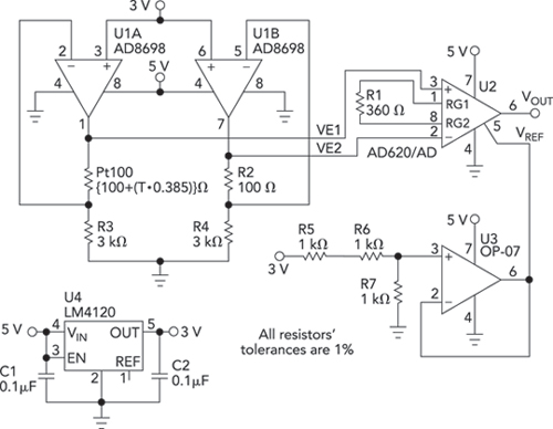
Temperature sens ors such as RTDs produce small resistance changes as a function of temperature. You can linearize a bridge circuit`s output by adding external linearizing circuits. But adding op amps to linearize the output means you`ll need a bipolar power supply. The circuit in Figure 1 represents an active bridge providing a linear voltage output using a unipolar power supply. The circuit uses the popular Pt100 RTD, which has a resistance of 100 © at 0 °C. Its temperature coefficient of 0. 00385 ©/ ©/ C produces a 38. 5- © increase in resistance from 0 °C to 100 °C. Thus, the resistance is 138. 5 © at 100 °C. In Figure 1, resistors R3 and R4 convert the output from the 3-V power supply into two 1-mA constant currents, one in each branch of the bridge.
At 0 °C, the bridge is balanced and, thus, V1 V2 = 0 V. The equation below describes the circuit`s output: Figure 2 shows a simulation of the circuit`s output from 0 °C to 50 °C. If you use a passive bridge that produces a nonlinear resistance, then you still need linearizing circuits prior to digitizing the circuit`s analog output or you need to linearize the output in software after digitizing.
Resistive sensors require excitation current, which this circuit provides. A Pt100 RTD requires 1 mA of excitation current to get its specified performance. As the bridge voltage is 3 V, you get 1 mA through the RTD, for which the circuit consumes 0. 1 mW in the sensor. That low power dissipation minimizes self-heating, which can affect measurement accuracy. 🔗 External reference
Related Circuits

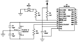
The circuit described is a crystal oscillation circuit using a CM OS inverting configuration, designed to ensure accurate operation. It employs a BCD counter (IC2) capable of achieving a maximum oscillation frequency of 2 MHz, which is 100 times...

The LA4440 is a two-channel audio power amplifier integrated circuit (IC) designed for stereo and bridge amplifier applications. In dual mode, it provides an output of 6 watts per channel, while in bridge mode, it can deliver up to...
The following file contains detailed information about the design of a basic clock oscillator circuit diagram. Included in this file is information about selecting the components. The clock oscillator circuit is a fundamental component in various electronic systems, providing a...
Bridged resistive sensing elements are commonly used in resistive type sensors and transducers. This type of sensor requires a biasing voltage to operate. The LM10 provides low... Bridged resistive sensing elements are integral components in various resistive sensors and transducers,...
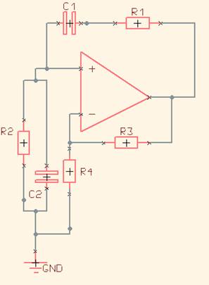
One of the simplest sine wave oscillators is the Wien Bridge Oscillator. Any circuit requires two conditions to oscillate. Tracing the path from the input, through the feedback network, and back to the input, there must be an overall...
The LVDS receiver requires a failsafe function to prevent an uncertain output state in the event of an improper connection. This application note explores the circuits and characteristics of three common failsafe functions: external biasing, in-path, and parallel. The LVDS...