
Line follower with atmega 16

The line follower robot circuit operates by using infrared (IR) sensors in the sensor module to detect the presence of a line on the ground. Typically, these sensors are positioned on the underside of the robot and are responsible for distinguishing between the line and the surrounding surface. When the sensors detect the line, they send signals to the microcontroller module, which is the central processing unit of the robot. The ATmega16 microcontroller processes the input from the sensors and determines the necessary actions to keep the robot on track.
The microcontroller module is programmed to interpret the sensor data and control the outputs to the DC motor module. Depending on the input from the sensors, the microcontroller adjusts the speed and direction of the DC motors, allowing the robot to follow the line accurately. For instance, if the left sensor detects the line, the microcontroller may reduce the speed of the left motor or stop it entirely, while maintaining or increasing the speed of the right motor to steer the robot back onto the line.
The DC motor module consists of two DC motors that drive the wheels of the robot. Each motor is connected to a motor driver circuit, which allows the microcontroller to control the motors' speed and direction through PWM (Pulse Width Modulation) signals. This configuration enables smooth and responsive movement of the robot, ensuring that it can navigate curves and intersections effectively.
Overall, the combination of the sensor module, microcontroller module, and DC motor module creates an efficient and responsive line follower robot capable of autonomously navigating along a predetermined path. The design can be further enhanced by incorporating additional features such as speed control, obstacle detection, and more sophisticated algorithms for improved performance.Here the complete electrical circuit diagram of line follower robot which built based on ATmega16. There are three modules of line follower robot circuit that are sensor module, microcontroller module and DC motor module. 🔗 External reference
Related Circuits
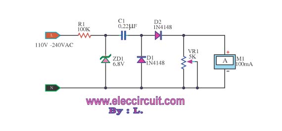
This meter displays the frequency of a power generator, which operates at a voltage range of 110V-240V and a frequency range of 10-100Hz. The output sine waves are converted to square waves. The described frequency meter is designed to accurately...
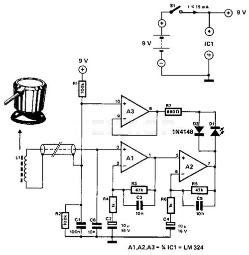
The circuit utilizes the principle that in an RL circuit, the pulse width across the inductor is proportional to the inductance. This circuit indirectly measures the inductance using a digital voltmeter (DVM). The measurement range is approximately 5 to...
This circuit is a church bell controller. Basic component is an ATmega32 microcontroller. At the circuit 1 24LC32 EEPROM memory is being used. As control, a menu is created that appears on a 4x20 LCD (Liquid Crystal Display). The...
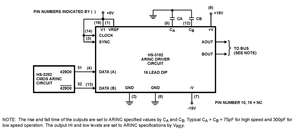
The HS-3182 is a monolithic dielectrically isolated bipolar differential line driver designed to meet the specifications of ARINC 429. This device is intended to be used with a companion chip, the HS-3282 CMOS ARINC Bus Interface Circuit, which provides...
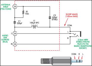
This document presents a concept for a low-cost adapter that enables the connection of a portable FM radio or MP3 player with an FM tuner to an external antenna and audio equipment, such as a hi-fi system or PC...
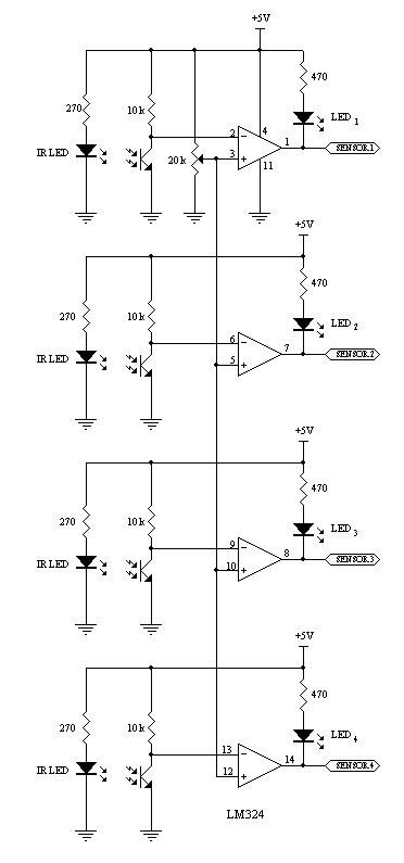
This robot utilizes two motors to control the rear wheels, while the single front wheel is free to move. It is equipped with four infrared sensors located on the underside to detect black tracking tape. When the sensors identify...