
Church bell Controller with ATmega32

This church bell controller circuit utilizes an ATmega32 microcontroller as its central processing unit, which is responsible for executing the programmed firmware. The microcontroller interfaces with a 24LC32 EEPROM, providing non-volatile storage for user-defined melodies, settings, and operational parameters. The system features a 4x20 LCD display for user interaction, allowing for a comprehensive menu-driven interface.
User input is facilitated through six tactile push buttons, which include functions for navigating the menu (Menu, Up, Down), confirming selections (Enter), and controlling the bell operation (Start, Stop). The firmware, written in C, is designed to be modular, with the potential for future enhancements without exceeding the 30 Kbyte flash memory limit of the microcontroller.
The circuit supports over 75 different melodies, which can be selected and programmed by the user. An integrated real-time clock (RTC) functionality is provided using a DS1307 chip, which ensures accurate timekeeping and includes a backup battery to maintain time during power outages. The system generates a pulse of 1 second every minute for the electromechanical clock, ensuring synchronization with real time.
Additional features include automatic correction for time loss during power outages, manual adjustments for the clock, and the ability to silence the bells during designated hours, accommodating for quiet periods in tourist areas. The user can modify the rhythm of the bells, and these settings are stored in the EEPROM for persistent memory retention.
The circuit is capable of controlling up to five bells and one clock, providing flexibility in operation. Overall, this church bell controller circuit combines robust functionality with user-friendly operation, making it a versatile solution for managing bell chimes in various settings.This circuit is a church bell controller. Basic component is an ATmega32 microcontroller. At the circuit 1 24LC32 eeprom memories is being used. As control I created a menu who will be appeared on 4x20 LCD (Liquid Crystal Display). The menu browsing can be done by 6 buttons at the face of the circuit's box (Menu, Up, Down, Enter, Start, Stop). The all firmware binds about 30Kbytes flash memory and can be increased by adding new features-functions.
This program has been written in C with CVAVR compiler. The idea of this circuit is being given by a friend of mine who has an foundry and he is building bells. I have made the PCB by my self. Features 1. More 75 different melodies (ADAM, PANYGJRJKO, AGJORJKO, etc) 2. Control of electrometrical clock of church with the production of pulse of duration 1Sec each one minute. 3. Automatic correction in case of power loss. 4. Percussion of clock each half but also entire hours, with possibility of choice of hours of silence (for tourist regions and hours of common quietness).
5. Manual correction of electromechanical clock. 6. All regulations become with the help of guidance (menu, up, down, enter, start, stop) 7. When it runs a rhythm we have the possibility of increase or decrease her speed, the information will stored in memory 24LC32. 8. Display time (DS1307), with backup battery. 9. All the in formations are displayed on 4X20 LCD. 10. Control up to 5 bells and 1 clock. 11. The user create his own program 🔗 External reference
Related Circuits
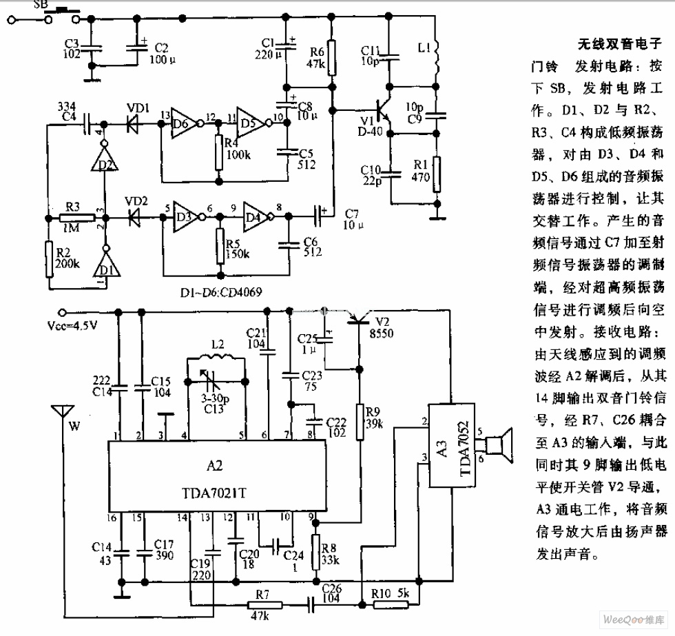
The transmitter circuit is activated by pressing the SB button. Components D1, D2, R2, R3, and C4 form a low-frequency oscillator that controls an audio oscillator made up of D3, D4, D5, and D6, allowing them to operate alternately....
The page is about equipping an Atmel AVR microcontroller based system with a Prism WLAN interface. This document is intended for people that already have experiences with the AVR microcontrollers and teaches them how to add a cheap but...

Usually we see Digital clock on LCD or 7 segment. But, this AVR Digital Clock which is designed by Ficara Emilio displayed on Oscilloscope. The project uses ATtiny 2313 as the main controller. What an interesting microcontroller project. Source...
The industrial fuel oil furnace controller circuit consists of a power supply circuit, a testing and ignition control circuit, and a control implementation circuit, as illustrated in the accompanying diagram. The power supply circuit includes a step-down capacitor (C6),...
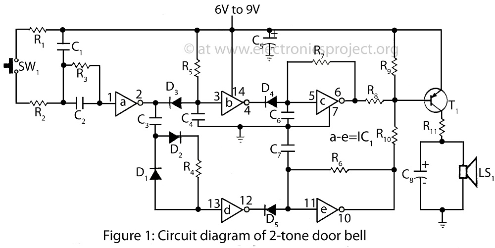
The project presented involves a verified circuit diagram for a two-tone doorbell that produces a "ding-dong" sound. It is part of a collection of various doorbell and alarm projects. The two-tone doorbell circuit typically utilizes a combination of capacitors, resistors,...
When the start button is pressed, the Arduino selects a random 4-digit code and flashes lights to indicate the code. If the user successfully repeats the code using the other buttons, the XBee module sends a message to another...