
Line Following Robot Sensor
The line-following robot sensor operates using infrared light to detect the presence of surfaces or lines beneath the robot. The sensor typically consists of an infrared LED and a photodiode or phototransistor. The LED emits infrared light, which is reflected by the surface below. The photodiode or phototransistor receives the reflected light, and the intensity of this light is used to determine the proximity of the surface.
In a typical application, the sensor is mounted on the underside of the robot. When the robot approaches a line or edge, the amount of reflected infrared light changes, allowing the robot's control system to make real-time adjustments to its movement. This feedback loop enables the robot to follow lines or navigate around obstacles effectively.
The circuit design for this sensor can include additional components such as resistors to limit current through the LED, capacitors for noise filtering, and operational amplifiers to enhance the signal from the photodiode. The output can be connected to a microcontroller or a simple comparator circuit to determine the appropriate response based on the detected signal.
Overall, the line-following robot sensor is an essential component for autonomous robotics, providing reliable surface detection in a compact form factor, enabling efficient navigation and obstacle avoidance.This Line Following Robot sensor or surface scanner for robots is a very simple, stamp-sized, short range (5-10mm) Infrared proximity detector wired around.. 🔗 External reference
Related Circuits

The circuit comprises an infrared sensor control circuit, a relay control circuit, a music generating circuit, and additional components. It is applicable for use in infrared alarms, timing control, and various other applications. The circuit design integrates several functional modules...
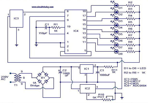
A digital temperature sensor circuit is explained with a circuit diagram. ICs ADC 0804, LM35, and LM317 are used in this digital circuit project. The digital temperature sensor circuit utilizes three primary integrated circuits (ICs): the ADC 0804, LM35, and...
The necessity for a device capable of autonomously detecting and extinguishing fires has become increasingly urgent. Many residential fires occur when individuals are either asleep or away from home. The development of such a device could significantly enhance the...
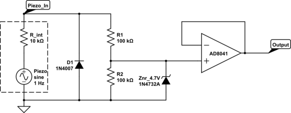
The intention is to utilize the sensor as a force sensor. It has been observed that the voltage output increases with the amount of pressure applied, although this output is only sustained for a brief period. This behavior is...
This is the circuit of a 500 watt linear amplifier, based upon a design by Frits Geerligs, PA0FRI, who has his own homepage at http://home.planet.nl/~fhvgeerligs. The circuit uses four PL519 TV line output valves in a very simple circuit...
Utilizing an analog audio line delay, it is possible to virtually adjust the size of a room. By simply turning a knob on the audio equipment, one can modify the perceived room size. The circuit described herein facilitates this...
Warning: include(partials/cookie-banner.php): Failed to open stream: Permission denied in /var/www/html/nextgr/view-circuit.php on line 713
Warning: include(): Failed opening 'partials/cookie-banner.php' for inclusion (include_path='.:/usr/share/php') in /var/www/html/nextgr/view-circuit.php on line 713