
avr Piezoelectric Sensor and the ADC

To integrate a piezoelectric sensor as a force sensor into a circuit with an ADC, it is essential to consider the voltage levels produced by the sensor under varying pressure conditions. The piezoelectric sensor generates a high output voltage, which can exceed 10 V under substantial force. However, the microcontroller's ADC input is limited to a maximum of 5 V. Therefore, a voltage divider or signal conditioning circuit is necessary to ensure that the voltage levels are safe for the microcontroller.
A voltage divider can be constructed using two resistors, R1 and R2, where the output voltage (Vout) is given by the formula:
\[ V_{out} = V_{in} \times \frac{R2}{R1 + R2} \]
In this case, R1 should be chosen to limit the maximum voltage to 5 V when the input (Vin) reaches 10 V. For example, if R1 is 10 kΩ and R2 is 5 kΩ, the output voltage can be calculated as follows:
\[ V_{out} = 10 V \times \frac{5 kΩ}{10 kΩ + 5 kΩ} = 3.33 V \]
This configuration ensures that even at maximum pressure, the output voltage remains within the safe operating limits of the microcontroller.
Additionally, it is important to implement a capacitor in parallel with the output to filter high-frequency noise and stabilize the voltage reading. A small capacitor (e.g., 1 µF) can help smooth out the transient spikes caused by the piezoelectric effect, allowing for more accurate ADC readings.
Finally, it is advisable to include a clamping diode circuit to protect the microcontroller from any potential voltage spikes that may occur when the sensor is subjected to sudden impacts. This can be achieved using a Zener diode rated for 5.1 V in parallel with the ADC input, which will clamp any excessive voltage and safeguard the microcontroller from damage.
In summary, the integration of the piezoelectric sensor into the ADC circuit requires careful consideration of voltage levels, the implementation of a voltage divider, filtering capacitors, and protective components to ensure reliable and safe operation.The reason being is that I would like to use the sensor as a force sensor. I noticed that the harder I press it, the higher a voltage it delivers (but for a very short time). This is expected behavior, of course. What I am wondering is how I would connect it to the ADC. I mean, when I press it really hard, the piezo registers upward of 10 V. When I press it softly, it usually gives me around 1. 3 V. As I understand it, the micrcontroller cannot take anything more than 5V, or else I run the risk of damaging it. Is this correct I mean, I am guessing the current coming out from the piezo is extremely small, though I don`t know if that changes the situation.
🔗 External reference
Related Circuits
The Resistive Sensor Head (A2053) is a Long-Wire Data Acquisition (LWDAQ) device that measures the resistance of up to eleven resistive sensors. These sensors can include 1000-Ω RTDs (Resistance Temperature Devices), 100-Ω RTDs, 120-Ω strain gauges, or similar resistive...
The following circuit illustrates the CD4017 integrated circuit (IC) used in an automatic room lights sensor circuit diagram. Features include a single light sensor utilizing two light-dependent resistors (LDRs). The CD4017 is a decade counter IC that can drive multiple...
The Atmel AVR series consists of high-quality microcontrollers featuring a comprehensive instruction set, which has led to the development of numerous effective compilers, eliminating the need to learn assembly language. One notable compiler is the BASCOM/AVR from MCS Electronics,...
To utilize the circuit, a wind vane similar to the one illustrated is required. It must feature a weighted front end and an air paddle at the rear. A small, strong magnet should be affixed to the front section...
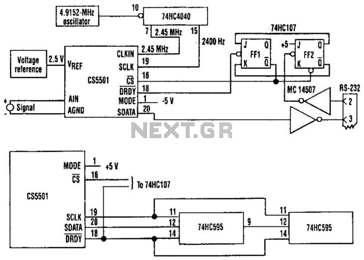
The CS5501 16-bit delta-sigma analog-to-digital converter continuously converts signals, outputting conversion words to its output register every 1024 cycles of its master clock, as it lacks a start convert command. By integrating a standard dual J-K flip-flop into the...
This is a straightforward liquid detector that utilizes a relay to activate an evacuation valve. It can be employed for water or any conductive liquid. The liquid detector circuit operates by leveraging the conductivity of liquids to trigger a relay....