
Line level to phono input
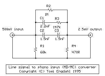
The circuit utilizes a basic configuration consisting of resistors and capacitors to achieve the desired attenuation and filtering. The signal level attenuation is accomplished through a voltage divider formed by two resistors, which reduces the input signal from 500 mV to 2.5 mV. The inverse RIAA filtering is implemented using a combination of capacitors and resistors arranged to create a frequency response that compensates for the RIAA curve, ensuring that the output signal maintains a flat frequency response across the audio spectrum.
For assembly, the components should be soldered onto a printed circuit board (PCB) or perfboard, ensuring proper connections and minimizing noise interference. The circuit can be housed in a metal enclosure to provide shielding against electromagnetic interference (EMI), which is particularly important for low-level audio signals. RCA connectors should be securely mounted to the enclosure for easy integration with audio equipment.
When constructing the circuit, attention should be given to the tolerance of the components. While the circuit can function adequately with standard 5% tolerance components, using tighter tolerance components (1% or better) may improve performance, particularly in high-fidelity applications. Additionally, the layout of the circuit should be optimized to reduce the length of signal paths, which can help minimize noise and distortion.
In conclusion, this circuit serves as an effective solution for converting high-level audio signals to a lower level suitable for phono inputs while ensuring the necessary frequency response through inverse RIAA filtering. Its simplicity and ease of assembly make it an accessible project for audio enthusiasts looking to enhance their vinyl playback systems.The circuit does two functions: signal level attenuation and inverse RIAA filtering. The signal attenuation is needed to convert the 500 mV signal to 2. 5 mV signal. The inverse-RIAA filtering is needed to make the frequency response of the system flat (same equalization that is used when music is transferred to vinyl in the studio). The picture bl ow shows the frequency response of the ideal inverse-RIAA filter: The picture below shows the circuit diagram of one channel. The other channel (for stereo) is identical. The circuit is so simple that you can easily build it by just soldering the components together and fit them to small metal box with the RCA audio connectors.
This circuit is a simplified version of circuit published in Elektor Electronics (T. Giesberts, Pick-up input becomes line input, Elektor Electronics, December 1995, page 99). The basic circuit idea is same, but my circuit is simpler and it does not use high-precision components. The performance is not the same, but I think that this circuit build even from 5% components is adequate for many purposes.
This part list is for the one channels described in the schematic. Usually you want stereo sound, in which case you have make two identical circuits: one for left channel and one for right channel. When you connect this circuit to your amplifier, set the phono input to MM or MD position (if it has a selector).
Keep in mind that phono input is much more prone to pick up interference, because signal levels in it are much lower than in line level inputs. Typically almost all receivers, and most integrateds have standard `low-gain` phono preamplifying sections (30dB to 38dB of gain typically).
These require the use of either moving magnet cartridges (typically in the 2. 0 to 5. 0mv range) or high output moving coil types (generally 1. 5 to 2. 0mV output). The better preamplifiers (and the odd integrated or receiver) accept low-output moving coil cartridges - which have outputs of. 2 to. 9mV. These high gain phono sections will typically have approx 55dB to 75dB of gain. MM (Moving Magnet) cartridges are designed to play into 47k ohms or higher input impedance. MM`s will typically be loaded with capacitive loading in the pF range. Moving magnet phono cartridges have a typical output of ~3mv at 47K Ohm load. Movin gmagnet cartriges are the ones most commonly used. Some very old (typically TUBE) equipments had phono input designed for high impedance and high output level CERAMIC cartridge.
These inputs were common 50 years ago, and disappeared with the introduction of stereo and transistors. These inputs have no RIAA EQ (ceramic pickups are amplitude-sensitive, and the RIAA curve produces (very) roughly a constant-amplitude cut).
A level of about 0. 1 volt should be fine for those. If you happen to have an equipment with CERAMIC cartridge input only, then you can`t use the circuit described above. You should be able to do the conversion with much simpler circuit, just a 1:10 signal level attenuator, for example something like my speaker level to line level converter.
🔗 External reference
Related Circuits
The designer requires a 1-Wire host computer IO framework that operates at 1.8V. Most 1-Wire devices are unable to function at this voltage. This application recommends implementing a 1.8V 1-Wire host computer alongside a 5V 1-Wire reference design for...
This meter displays the frequency of a power generator, which operates at a voltage range of 110V-240V and a frequency range of 10-100Hz. The output sine waves are converted to square waves. The described frequency meter is designed to accurately...
This analog switch circuit is designed to switch an analog line on or off. It consists of two analog switches in integrated circuit (IC) form that are controlled by two pushbuttons. The described analog switch circuit utilizes two integrated analog...
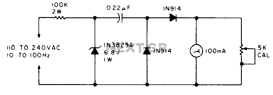
The meter will display the frequency from a power generator. Incoming sine waves are transformed into square waves by the 100K resistor and the 6.8 V zener diode. The square wave is differentiated by the capacitor, and the current...
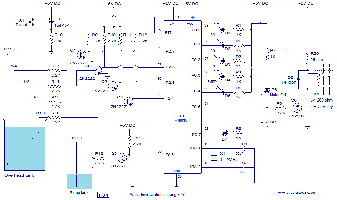
A water level controller based on the 8051 microcontroller is presented in this article. While numerous water level controller projects have been published on this website, this is the first one utilizing a microcontroller. The water level controller monitors...
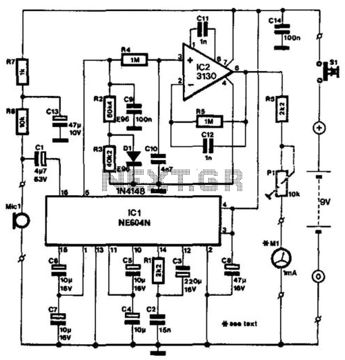
The NE604's signal-strength indicator section utilizes an internal logarithmic converter, allowing for a linear decibel scale. This feature enables the replacement of the moving-coil meter depicted in the diagram with a digital instrument. The assumed signal source is an...