
Water level controller using 8051
The water level controller circuit employs a microcontroller-based design to efficiently manage the operation of a water pump based on the water levels in both the overhead tank and the sump tank. The system is equipped with multiple sensor probes, each corresponding to specific water levels in the overhead tank, which communicate with the microcontroller through transistor interfaces. This arrangement allows precise monitoring and control of the water levels.
The probes are strategically placed to detect the water levels at 1/4, 1/2, 3/4, and FULL, enabling the microcontroller to ascertain the exact status of the tank. The use of transistors as switches provides electrical isolation and amplifies the signals from the probes, ensuring reliable operation of the control logic. The microcontroller continuously scans the input from the probes, interpreting the voltage levels at the corresponding port pins to determine whether the tank is empty, partially filled, or full.
The control logic includes safety features to prevent the pump from operating under unsafe conditions. If the sump tank level is low, the pump will not activate, preventing potential damage to the pump and ensuring efficient water usage. The incorporation of LEDs provides visual feedback on the system’s status, with specific indicators for pump operation and low sump conditions.
The relay used for controlling the pump provides a robust means of switching the higher power required by the pump, while the microcontroller handles the low power control signals. This design enhances the reliability and functionality of the water level controller, making it suitable for various applications in residential and industrial settings. The circuit diagram serves as a visual representation of the components and their interconnections, aiding in both understanding and implementation of the system.A water level controller based using 8051 is shown in this article. A lot of water level controller projects have been published in this website but the is the first one based on a microcontroller. This water level controller monitors the level of the over head tank and automatically switches on the water pump when ever the level goes below a pres
et limit. The level of the over head tank is indicated using 5 leds and the pump is switched of when the over head tank is filled. The pump is not allowed to start if the water level in the sump tank is low and also the pump is switched off when the level inside the sump tank goes low during a pumping cycle.
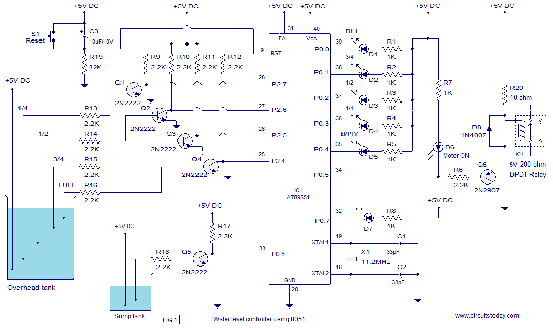
The circuit diagram of the water level controller is shown below. The level sensor probes for the overhead tank are interfaced to the port 2 of the microcontroller through transistors. Have a look at the sensor probe arrangement for the overhead tank in Fig1. A positive voltage supply probe goes to the down bottom of the tank. The probes for sensing 1/4, 1/2, 3/4 and FULL levels are placed with equal spacing one by one above the bottom positive probe.
Consider the topmost (full level) probe, its other end is connected to the base of transistor Q4 through resistor R16. Whenever water rises to the full level current flows into the base of transistor Q4 which makes it ON and so its collector voltage goes low.
The collector of Q4 is connected to P2. 4 and a low voltage at P2. 4 means the over head tank is not FULL. When water level goes below the full level probe, the base of Q2 becomes open making it OFF. Now its collector voltage goes high and high at P2. 4 means the tank is not full. The same applies to other sensor probes (3/4, 1/2, 1/4) and the microprocessor understands the current level by scanning the port pins P2. 4, P2. 5, P2. 6 and P2. 7. All these port pin are high (all sensor probes are open) means the tank is empty. Port pin P0. 5 is used to control the pump. When ever it is required start pumping, the controller makes P0. 5 low which makes transistor Q6 ON which in turn activates the relay K1 that switches the pump. Also the LED d6 glows indicating the motor is ON. LED D7 is the low sump indicator. When the water level in the sump tank goes low, the controller makes P0. 7 low which makes LED D7 to glow. The circuit diagram of the water level controller is shown in the figure below. 🔗 External reference
Related Circuits
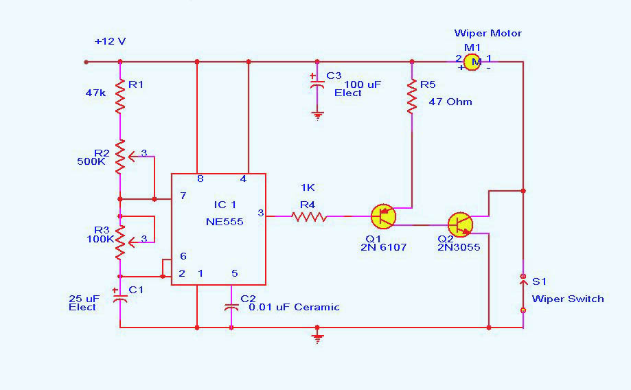
DC motor control circuit using NE555. The 555 timer circuit has numerous applications. For those unfamiliar with its functionalities, an authoritative book can provide valuable insights. CircuitsToday offers an online store featuring reviews of three highly recommended books that...
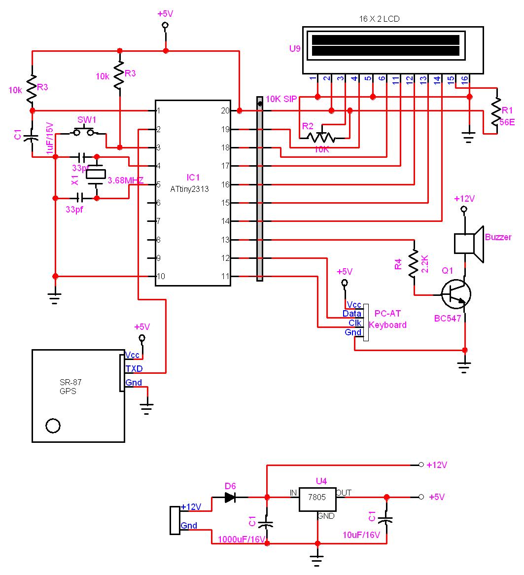
In this project, a GPS module is interfaced with an AVR microcontroller. The ATtiny2313 retrieves location data from the GPS and displays it on an LCD screen. The project involves the integration of a GPS module with the ATtiny2313 microcontroller,...
The anti-theft system includes two frequency sirens connected to the vehicle's immobilizer system. In the laboratory simulation model, the changes in operating modes, siren activation, and fuel supply cut-off are indicated by the illumination of LEDs and communicated to...
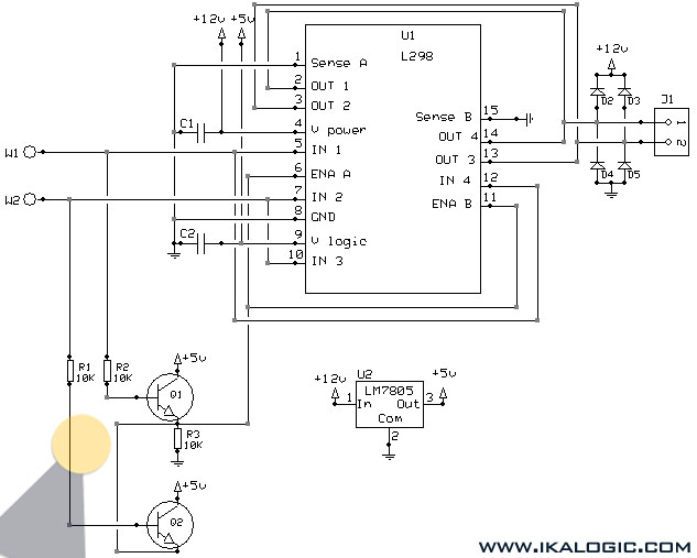
This implementation utilizes the L298 integrated circuit to drive motors and inductive loads with a continuous current capacity of up to 4A. The L298 consists of two independent channels, each capable of driving loads of up to 2A. By...
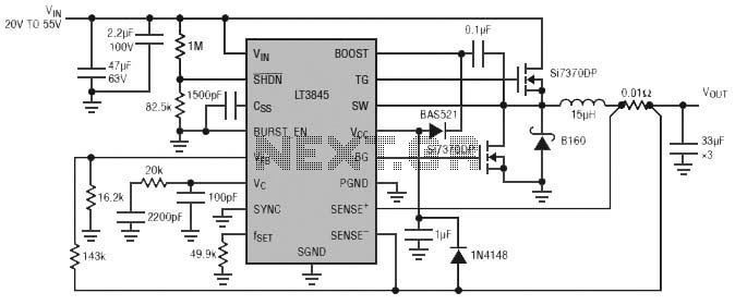
Burst Mode operation maintains high efficiency at light loads by reducing IC quiescent current to 120 µA. Light load efficiency is also improved with the reverse inductor current inhibit function, which supports discontinuous operation. Additional features include an adjustable...
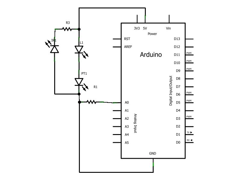
Have you ever wanted to create a line-following robot but found infrared sensors too expensive? If you are located in the UK and have access to a Maplin store nearby, you can purchase infrared transmitters and receivers for just...