
Line Ripple Clock

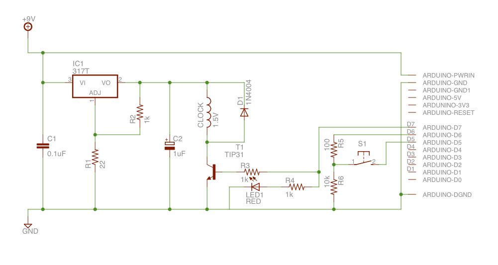
The described circuit utilizes a wall wart power supply, which typically outputs a DC voltage with some ripple. This ripple is undesirable for precise applications, such as timing circuits found in digital clocks. The primary function of the circuit is to convert this ripple into a stable signal suitable for driving a digital clock that operates at double the line frequency, hence the term "Line x 2."
The circuit likely employs a combination of filtering and signal conditioning techniques to achieve the desired output. Initially, the AC voltage from the wall wart is rectified, possibly using a bridge rectifier configuration. This rectification process converts the AC voltage into a pulsating DC voltage. However, instead of traditional filtering methods that would involve significant components to smooth the output, this circuit may utilize a combination of capacitors and possibly inductors to reduce the ripple effectively.
Following the filtering stage, a voltage regulator may be implemented to ensure that the output voltage remains stable, regardless of variations in the input voltage from the wall wart. This regulator can also provide the necessary isolation from the AC mains, enhancing safety and reducing electromagnetic interference.
To generate the clean line frequency sine wave, the circuit may include a phase-locked loop (PLL) or a microcontroller configured for frequency synthesis. This allows the clock to maintain accurate timekeeping without the need for direct AC input, which simplifies the design and reduces potential points of failure.
Overall, this circuit design is efficient and practical for powering digital clocks, ensuring that the output is not only clean but also reliable, thus eliminating the complexities associated with traditional AC input methods.This circuit converts the ripple from a wall wart supply to a clean Line x 2 digitial clock. Doing it this way eliminates the need to put AC into the unit which then has to be rectified and filtered just to have access to the line frequency sine wave. 🔗 External reference
Related Circuits
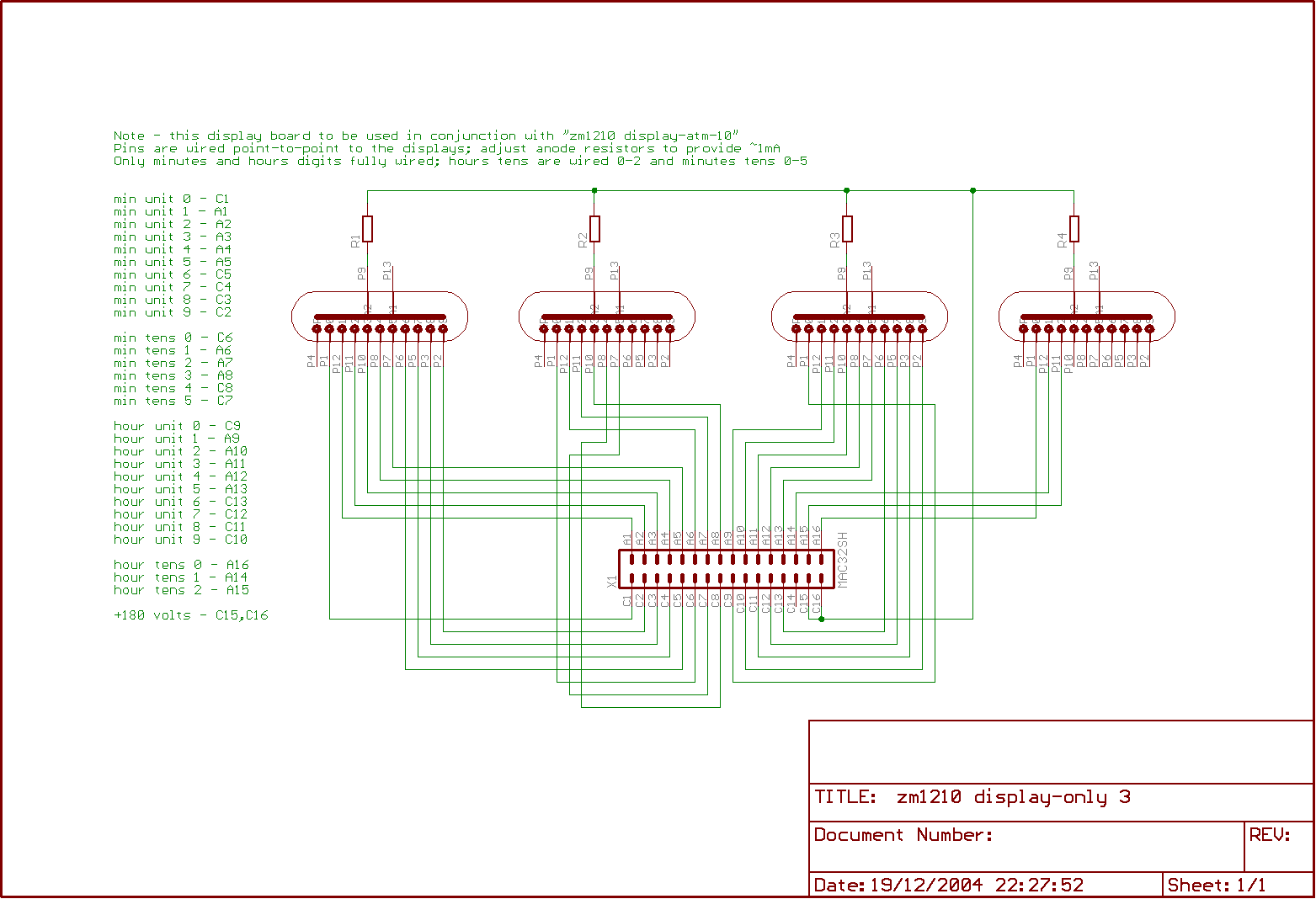
The clock is built on two boards; one contains the high-tension generator and the processor logic, while the other accommodates the tubes. This design offers a more compact layout compared to the previous model, although it does not save...
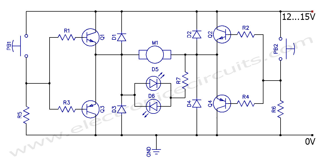
This circuit can control the direction of a DC motor, allowing it to operate in both clockwise and counterclockwise directions (forward and backward). The described circuit employs an H-bridge configuration, which is essential for reversing the polarity of the voltage...
This project is a mixer designed for three or more input lines. For configurations with more than three inputs, the input sections can be duplicated (using P=10K and R=22K). It is powered by a 9V DC source. The mixer circuit...
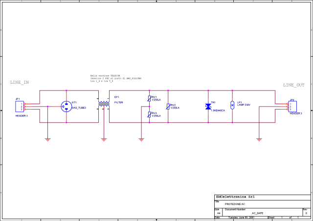
What is a circuit breaker? When is an AC power line filter or a phone line filter necessary? How can a noise filter be designed? Is it possible to create a homemade surge protector? The following circuit protection options...
Upon purchasing the slave dial, it arrived without instructions, packaging, or additional details. The only visible markings, aside from decades of grime, were on the face (SMITH SECTRIC, ACELEC SYDNEY) and some markings on the bracket holding the mechanism...
The project involves the creation of a line-follower robot. This microcontroller-based robot is designed to follow a black line on the ground. The line-follower robot utilizes a microcontroller as its central processing unit, which interprets input signals from various sensors...