
Linear Amp Project HF VHF UHF Amplifier
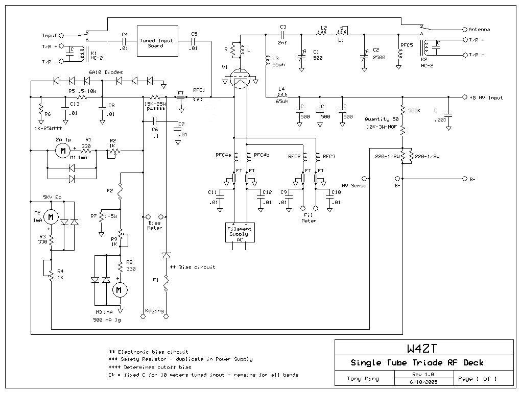
The GS-35B tube is a high-performance vacuum tube that is often used in radio frequency applications. The filament burn-in jig is essential for ensuring the longevity and reliability of these tubes by properly conditioning them before use. The design of the filament choke and cathode choke is critical to maintaining balanced currents and minimizing noise in the output signal. The bifilar winding method is particularly effective for reducing electromagnetic interference, as it helps to cancel out the magnetic fields generated by the currents flowing through the wires.
The recommended construction techniques for the chokes involve careful attention to the dimensions and materials used. The choice of #18 wire is suitable for the desired current handling and inductance characteristics. The ferrite rods are chosen for their magnetic properties, which enhance the inductance of the chokes. Proper cooling is also a vital aspect of the design; ensuring that the airflow is sufficient will prevent overheating and potential damage to the tube.
In conclusion, the tube tester and filament burn-in jig is an essential tool for anyone working with GS-35B tubes or similar high-power vacuum tubes. Its design considerations, including the use of separate chokes and adequate cooling methods, contribute to the overall performance and reliability of the amplifier systems in which these tubes are utilized.Tube Tester and Filament Burn In Jig - Here`s my answer to cooking the tubes for days and then testing them before inserting them in an amp. Note - I have learned an important lesson with this jig. The filament alone heats the entire bottom of this tube and even with the fan blowing air into the box, the bottom of the tube will get too hot to hold
in your hand. This is an important lesson regarding cooling of the tube, particularly the grid ring and filament seals. Do NOT run this tube without air, lots of air, blowing around its base and through the anode cooler. There is 38 watts of heat from the filament alone. W4ZT GS-35B Tubes Glow In The Dark! - Pictures of GS-35Bs glowing in the dark producing a rainbow of color. Do yours glow My bet is that they do. What color are they Want to share your pictures NOTE: Do NOT use a center tap filament transformer. To do so leads to unbalanced currents in the filament choke and hum modulation of the RF output. Instead, use a separate cathode choke. Note that the filament choke can be made with two 48" long pieces of #18 wire bifilar wound to fit on a 3.
5" length of 3/8" ferrite rod. The cathode choke can be one 48" length of #18 wire on a 1. 5" length of 3/8" ferrite rod. Both chokes are about 25 to 30 uH. Be careful to wind the chokes on a metal rod slightly smaller than the ferrite and then move them to the ferrite rod to prevent breaking the ferrite. Was at this address but Chuck changed his ISP to MSN. MSN wants you to sign up to view his pages so they are no longer available by direct link. You can still view this page by using the Wayback Machine at which will take you here: Chuck`s program was here but now can only be seen by using the Wayback Machine at which will take you here: AG6K - Rich has lots of amp building info on his site.
Years of experience and knowledge to share. See the pictures of the ugly amps, etc. There`s a great multi-part article on amplifiers that he put together for the ARRL Handbook. Read, if you dare, about Richard Measures` clash with ARRL over his writing about amps, advertiser control of QST and other interesting stuff. (W4BD) NOTE: Do NOT use a center tap filament transformer. To do so leads to unbalanced currents in the filament choke and hum modulation of the RF output. Instead, use a separate cathode choke. Note that the filament choke can be made with two 48" long pieces of #18 wire bifilar wound to fit on a 3.
5" length of 3/8" ferrite rod. The cathode choke can be one 48" length of #18 wire on a 1. 5" length of 3/8" ferrite rod. Both chokes are about 25 to 30 uH. Be careful to wind the chokes on a metal rod slightly smaller than the ferrite and then move them to the ferrite rod to prevent breaking the ferrite. eHam. net - Other hams review the GS-35B. W2APE swaps out an 8877 with a GS-35B in his Harris AM-7224/URC. After a few changes he is highly pleased with the update: 🔗 External reference
Related Circuits
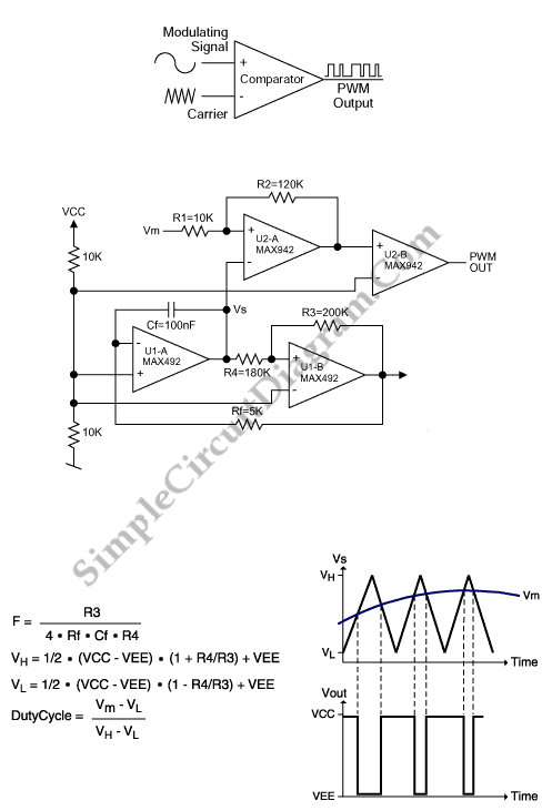
This is a simple PWM modulator circuit. Comparing the message signal to a ramp or triangular waveform is the simplest way to produce a PWM signal. When the... The PWM (Pulse Width Modulation) modulator circuit operates by comparing a modulating...
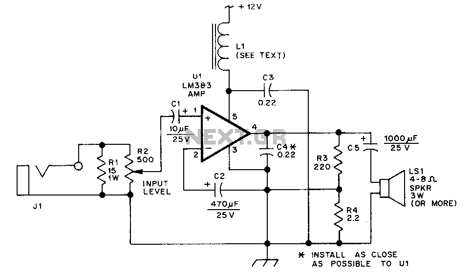
The LM383 is an audio power amplifier capable of delivering up to 8 watts of audio output. Resistor R1 serves as a load resistor for the audio output of a hand-held transceiver. Resistor R2 can be implemented using two...
Since then, NL has evolved into the Microsoft Windows®-based NL4, which has been extensively used by world-class engineers in various fields of electronics for almost 10 years. NL5 is the first version to be publicly available. Unlike conventional SPICE-based...
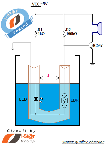
How to measure water purity and test water quality using a simple electronics project. Water purity measurement and water quality analysis can be performed using a water purity checker circuit. This circuit is constructed around a Light Dependent Resistor...
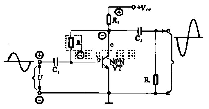
A common series negative feedback amplifier is depicted in this configuration. In this amplifier, R acts as the resistor for the negative feedback element, which is part of the input circuit. The output circuit is linked to both the...
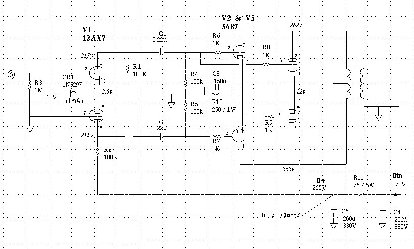
This stereo amp will give you 4-8W/ch of zero feedback triode power for less than a pair of Chinese 300B's if you know where to shop. For those of you who are unfamiliar with this tube, the 5687 is...