
Common series negative feedback amplifier
The common series negative feedback amplifier operates by utilizing a negative feedback loop to enhance stability and control over the gain of the amplifier. The resistor R, positioned in the feedback path, plays a crucial role in determining the overall gain of the circuit. By introducing feedback, the amplifier can correct for variations in input signal levels, ensuring a more consistent output.
When a positive input signal is applied, the transistor's emitter voltage rises, reflecting the input voltage. This relationship is critical for understanding how the amplifier processes signals. The feedback resistor R diminishes the input signal, effectively lowering the voltage at the base-emitter junction to Ube. The negative feedback introduced by R counteracts any fluctuations in input signal, stabilizing the amplifier's performance.
Furthermore, the coupling capacitor C facilitates AC signals by bypassing the negative feedback for alternating current. This configuration allows AC signals to pass through without the influence of the feedback loop, enabling the amplifier to achieve a higher gain for AC applications while maintaining stability for DC signals.
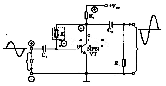
In summary, the common series negative feedback amplifier is a versatile circuit that utilizes negative feedback and coupling capacitors to optimize performance across different signal types. The careful selection of resistor R and capacitor C values is essential for achieving the desired amplification characteristics while ensuring stability and reliability in the amplifier's operation. Common series negative feedback amplifier (2) series negative feedback amplifier shown in series is a common negative feedback amplifier. Wherein R is the resistor current nega tive feedback element, because it belongs to the input circuit, output circuit belongs to the input and output circuit linked up. First, assume that an instantaneous input signal is positive (+), due to the emitter (e) of the polarity of the voltage to the base (b) the same, but also for the positive (+), increases the potential of the transistor emitter.
Because the emitter voltage is equal to the input voltage Ub {-U-Uf, through feedback element R, weaken the input signal into a voltage Ube, so negative feedback is feedback elements R. A negative feedback resistor R is used to stabilize the amplifier, the greater the resistance, the entire amplifier is smaller magnification.
And a negative feedback resistor R is connected in parallel to a capacitor coupling capacitor C, corresponds to the AC emitter (e) of the short-circuit, the AC signal has no negative feedback, thereby to obtain a larger magnification AC
Related Circuits
This article discusses several opamp-based headphone amplifier circuits, including suggestions for selecting opamps, input coupling and filtering, high current output stages and power supply options. There are no recommendations for specific opamp brands or models. For tube devotees, there...
A general purpose audio power amplifier is a must have for the electronics amateur. It's not a good thing to use your HiFi set for an experiment, when there's a risk of blowing its transistor out. Amplifier for your...
This circuit enables the display of an ECG signal on an oscilloscope. Operational amplifiers IC1a, IC1b, and IC1d create an instrumentation amplifier with a gain of 201. IC1c amplifies the common-mode signal by a factor of 31 and supplies...
Input current (from sensors connected to the patient) is limited to less than 5 µA under fault conditions. Note that Avol = 25 single Ni-cad battery operation. The circuit is designed to ensure that the input current from patient-connected sensors...
Where can one obtain a 12AX7 tube? These tubes are very popular for use in the preamplifier stages of many professional electric guitar amplifiers. A good music store will have them available for a modest price (around $12 US...
To commemorate the hundredth design posted on this website and to meet the requests of numerous correspondents desiring a more powerful amplifier than the 25W MosFet, a 60 - 90W high-quality power amplifier design is presented. The circuit topology...