
PWM Modulator Using Op-Amp

The PWM (Pulse Width Modulation) modulator circuit operates by comparing a modulating signal, often referred to as the message signal, with a reference waveform that is typically a ramp or triangular signal. This comparison is crucial for generating a PWM signal, which varies the width of the pulses in accordance with the amplitude of the message signal.
In a typical configuration, the circuit may employ an operational amplifier (op-amp) in a comparator setup. The non-inverting terminal of the op-amp receives the message signal, while the inverting terminal is connected to the ramp or triangular waveform generator. The output of the op-amp will switch between high and low states based on the relationship between the two inputs. When the message signal exceeds the ramp signal, the output transitions to a high state, producing a pulse. Conversely, when the message signal falls below the ramp signal, the output returns to a low state, resulting in the cessation of the pulse.
The frequency of the PWM signal is determined by the frequency of the ramp or triangular waveform, while the duty cycle of the PWM output is directly proportional to the amplitude of the message signal. This relationship allows for efficient control of power delivered to loads, such as in motor speed control applications or in dimming LED lights.
Additional components, such as resistors and capacitors, may be included in the circuit to filter noise or stabilize the output. The design can be fine-tuned by adjusting the reference waveform's frequency and amplitude, which affects the performance characteristics of the PWM modulator. Overall, this simple PWM modulator circuit is a fundamental building block in various electronic applications, providing an effective means of controlling power and signal modulation.This is a simple PWM modulator circuit. Comparing the message signal to a ramp or triangular waveform is the simplest way to produce a PWM signal. When the.. 🔗 External reference
Related Circuits

A bicycle typically does not have a turning light. When a cyclist wants to turn, it can be dangerous as vehicles following may not be aware of the turn. To enhance safety, a turning light circuit for bicycles can...
The induction coil detects the magnetic field flux during phone calls, amplifies the signal, and triggers the LED. These circuits are designed for the phone to rest on the pickup coil. The electromotive force (emf) from the bell electromagnets...

The circuit is designed to enable rapid changes in motor speed and direction by utilizing four outputs to drive a MOSFET H-bridge. The lower rail power MOSFETs are N-channel devices, while the upper rail MOSFETs are P-channel. All MOSFETs...

A few months ago, a search was conducted for an easy-to-build PWM inverter that does not require any PIC programming. The investigation led to a consideration of a 555 PWM amplifier circuit. The 555 timer IC is widely used in...
Tools that feature the equivalent of a professional, easy-to-use, cheaper, and, more importantly, safe for use. They are designed for checking and identifying AC voltages of 220 Volt or 120 Volt. The tools mentioned are essential for ensuring electrical safety...
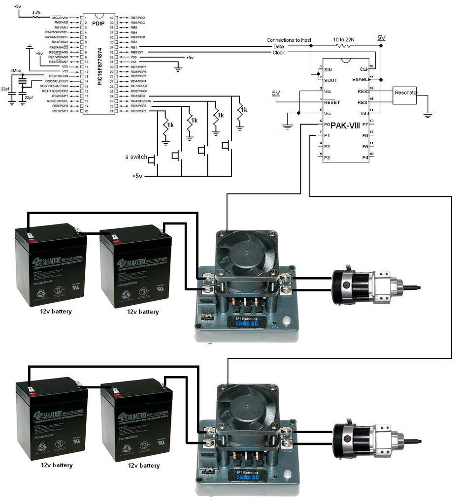
Build a large dancing robot. This was intended to be a walking robot, but it ended up moving in a more rhythmic manner. A video is available in the last step. The project involves the construction of a large dancing...