
10 led VU Meter using LM3915

The described circuit operates on a principle of visual signal representation using a VU meter configuration. The core component, the LM3915, is a dot/bar graph display driver that can illuminate up to 10 LEDs in response to an input voltage. This IC is particularly suited for audio level indication, providing a clear visual representation of signal strength.
The circuit begins with the input signal, which is fed into the TL071 operational amplifier. This op-amp is configured for half-wave rectification, ensuring that only the positive half of the input waveform is processed. This rectified output is then fed into the LM3915, which interprets the voltage level and activates the corresponding number of LEDs based on the input signal strength.
The switch S1 introduces versatility to the circuit by allowing users to select different voltage ranges for indication. This feature is essential for applications where varying signal levels need to be monitored. The circuit can effectively display levels from as low as 60 mV, suitable for low-level audio signals, up to 25 V, accommodating higher voltage signals.
In terms of component selection, the TL071 is favored for its low noise and high precision, making it ideal for audio applications. The LM3915's ability to drive multiple LEDs without additional components simplifies the design and reduces potential points of failure.
Overall, this circuit design provides a reliable and visually intuitive method for monitoring signal levels, making it suitable for various electronic applications, including audio equipment, signal processing, and general voltage level monitoring.Circuit diagram is a very simple circuit-level indication, with 10 Led. Used a series of half-wave rectification of precision around IC2 TL071, with a single. LM3915 IC is used to control the led, as an indicator VU Meter. LM3915 can be controlled 10 led. With the switch S1, we can choose an indication from the LED. Level mV into a 60-1st, 25 V. T he following is a schematic drawing: 🔗 External reference
Related Circuits
This tester is designed to locate stray electromagnetic (EM) fields. It will easily detect both audio and RF signals up to frequencies of around 100kHz. Note, however that this circuit is NOT a metal detector, but will detect metal...
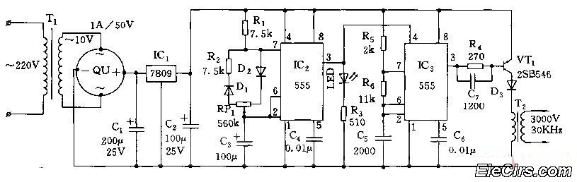
Adjust the RP1 to modify the pulse duty cycle of IC2, which in turn alters the pulse oscillation time of IC3. This regulation allows for the control of ozone generation time, effectively changing the concentration of ozone in the...
The transceiver switches the four-element 1500-ohm crystal band-pass filter (BPF) connections between the inputs and outputs of two SA602 integrated circuits to reverse the signal flow for receive/transmit (R/T) operation. Since no intermediate frequency (IF) amplifier is utilized in...

This is a circuit design for an FSK demodulator, which is an electronic device that converts an FSK signal into a serial digital signal. FSK modulation is used to transmit digital serial data, and demodulation is necessary to retrieve...
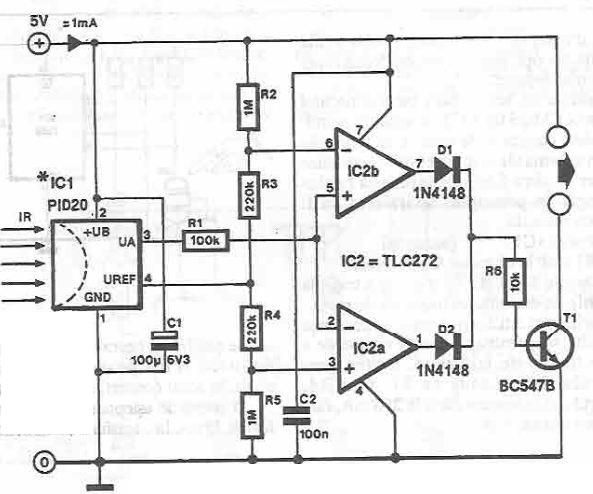
This infrared detector circuit utilizes the PID20 integrated circuit manufactured by Siemens, which converts thermal radiation into electrical impulses. It includes an operational amplifier and several electronic components. The output signal at pin 3 is compared to a reference...
This is a simple circuit where an LED turns on only after a predetermined time once the power supply is activated. Initially, when the power supply is turned on, the transistor remains off. The capacitor charges through the preset...