
1W Linear FM Booster
The RF amplifier described is designed for enhancing the signal strength of small FM transmitters and similar devices, commonly referred to as "bugs." The circuit utilizes two Philips 2N4427 transistors, which are known for their high frequency and power handling capabilities. The amplifier is rated at approximately 1 Watt output power, making it suitable for driving linear amplifiers like the BGY133 or BLY87, which can further increase the output power to meet specific transmission needs.
The power supply requirements for this amplifier are critical; it must provide a current of 500 mA at a nominal voltage of 12 Volts. While increasing the supply voltage can enhance the transmission range, caution is advised as exceeding 15 Volts can lead to overheating and premature failure of the transistors. Therefore, maintaining the voltage within the specified range is essential for reliable operation.
The amplifier is optimized for operation within the frequency range of 80 MHz to 110 MHz, providing a gain of 15 dB in this bandwidth. This characteristic makes it effective for FM broadcasting applications. The design includes three inductors, L4, L5, and L6, which are constructed as air coils with a diameter of 5 mm and consist of 8 turns of 1 mm diameter wire. These coils are integral to the tuning and stability of the amplifier, ensuring efficient signal amplification.
Overall, this RF amplifier design is straightforward and yields significant results, making it an attractive project for hobbyists and professionals looking to enhance their FM transmission capabilities. Proper assembly and adherence to the specified voltage and current parameters will ensure optimal performance and longevity of the circuit.That RF Amplifier is for boosting small fm transmitters and bugs. It use two Philips 2N4427 and its power is about 1Watt. At the output you can drive any linear with BGY133 or BLY87 and so on. Its power supply has to give 500mA current at 12 Volts. More voltage can boost the distance but the transistors will be burned much earlier than usual.! In any case do not exceed the 15Volts.
The Amp offers 15 dB in the area of 80Mhz to 110 Mhz. L4, L5, and L6 are 5mm diameter air coils, 8 turns, with wire 1mm wire diameter.An easy project, with great results.
🔗 External referenceRelated Circuits
The SP1481E, SP1485E, SP1490E, and SP1491E series transceivers, combined with the SP6652 high-efficiency, high-frequency current mode PWM buck regulator, facilitate the creation of an isolated RS-485 interface capable of providing up to 2kVrms isolation. This configuration supports CAN communication...
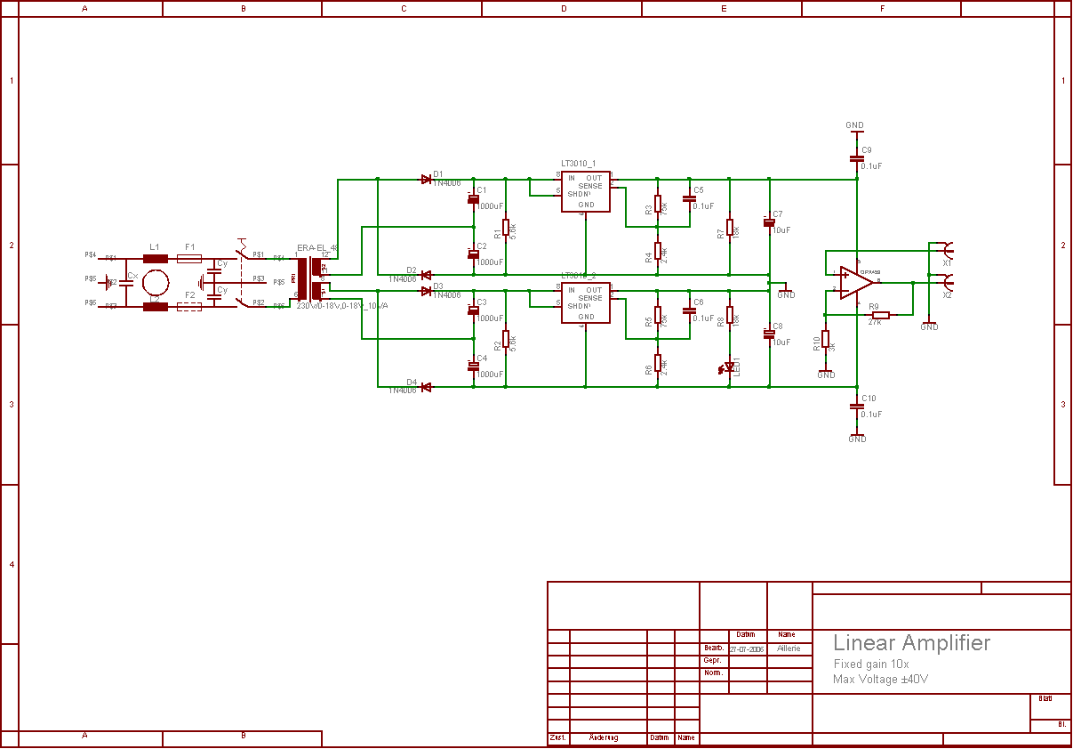
The aim of this project was to develop a linear analogue amplifier designed for laboratory use. This amplifier has to realise a voltage amplification of 10x and is intended to amplify function generator signals for tests. Power supply requirements:...
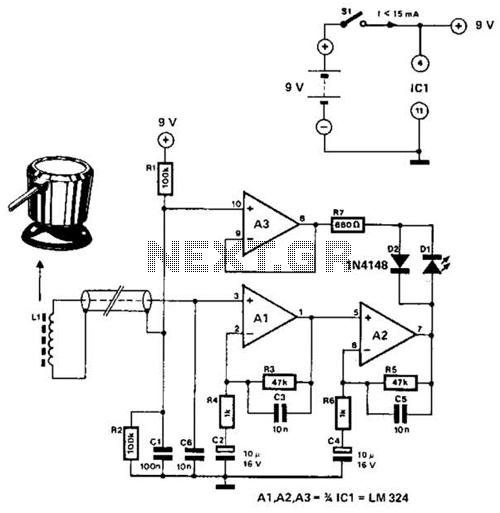
The circuit utilizes the principle that in an RL circuit, the pulse width across the inductor is proportional to the inductance. This circuit indirectly measures the inductance using a digital voltmeter (DVM). The measurement range is approximately 5 to...
This schematic represents a cable TV signal booster amplifier circuit designed to enhance the signal strength of a cable TV system. It is recommended to use 75 Ohm coaxial cables for both the input and output connections, and the...
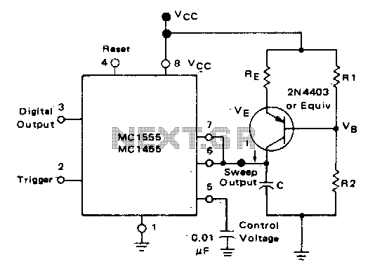
In the monostable mode, the resistor can be replaced by a constant current source to provide a linear ramp voltage. The capacitor still charges from 0 to 2/3 Vcc. In a monostable multivibrator configuration, the circuit typically consists of a...
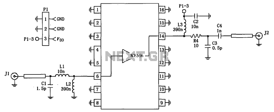
The impedance linear amplifier circuit is illustrated in FIG 75 and is configured using the RF2320 component. Connectors J1 and J2 are 75-ohm connectors. The impedance linear amplifier circuit designed with the RF2320 is intended for applications requiring high fidelity...