
simple 555 timer circuit

The described circuit utilizes a 555 timer IC configured in astable mode, which allows it to generate a continuous square wave output. The frequency and duty cycle of the oscillation are primarily determined by the capacitor and resistor values connected to the timer.
In this configuration, two timing capacitors (C1 and C2) are employed, where replacing the 220 µF capacitor with a 1000 µF capacitor increases the time period of the oscillation, thus slowing down the output frequency. Conversely, substituting in a 150 µF capacitor will reduce the time period, resulting in a faster oscillation frequency.
The resistor R1 plays a critical role in defining the charge and discharge times of the timing capacitor. By experimenting with different resistor values, such as 470 ohms or 910 ohms, the user can fine-tune the frequency of the output signal to meet specific application requirements.
The 555 timer circuit is widely used due to its versatility and ease of implementation in various electronic applications. It can be utilized in strobe lights, tone generators, and pulse-width modulation applications, among others. Proper selection of components allows for customization of the output characteristics, making it suitable for different tasks within electronic projects.
For optimal performance, ensure all connections are secure and components are rated appropriately for the voltage and current levels in use.This is a simple 555 circuit perfect for osculating circuits if you wont the strobe slower swap the 220uf capacitors for some 1000uf capacitors and if you wont it faster try some 150uf capacitor and you can also change out R1 to, try 470 or 910 ohms and if you have any questions ask my by leaving your questions in the comment box or email me at er icgoodchild@yahoo. com 🔗 External reference
Related Circuits
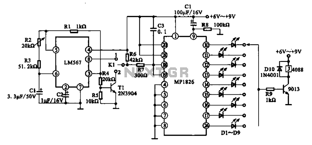
A precision circuit utilizing the LM567 timer, specifically the MPI826, where the LM567 functions as a dual-band oscillator. The MP1826 serves as a divider in the circuit, allowing the output signal from the LM567 to achieve extended timing. The...
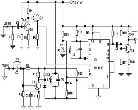
The following circuit illustrates a simple TV transmitter circuit diagram. This circuit is based on the LM1889 integrated circuit (IC). Features include quadrature chroma modulators and RF capabilities. The circuit utilizes the LM1889 IC, which is designed for television applications,...
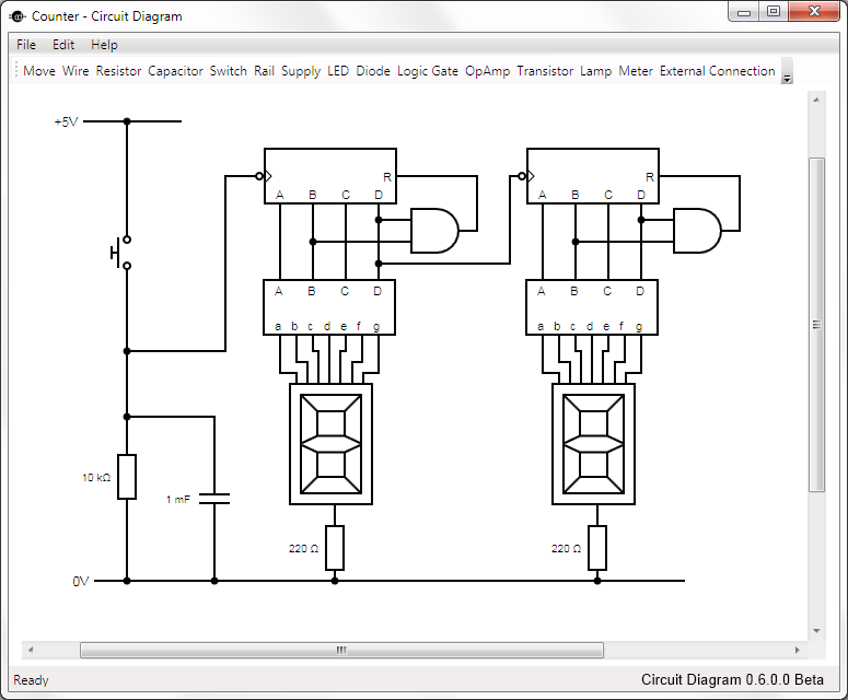
This is Circuit Diagram 0.1 Alpha Software, available for free download and open source. The Circuit Diagram 0.1 Alpha Software is designed as an intuitive platform for creating and editing electronic circuit schematics. It provides users with a variety of...
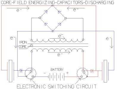
so what happens when you flip a switch? When you try to stop the flow of current in 'zero' time its equivalent to trying to stop a freight train instantaneously. you get a huge voltage buildup "dv/dt" = "X/0=infinity...
Anyone who has designed circuits using the 555 timer chip has, at some point, wished for the ability to program longer timing periods. Timing intervals exceeding a few minutes are challenging to achieve due to the significant impact of...
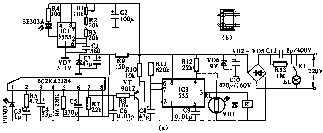
This circuit utilizes the KA2184 infrared receiver ASIC for an infrared remote control dimmer light application, as depicted in the schematic. The infrared signal is generated by a pulse generator using an NE555 timer integrated circuit. The NE555 produces...