
Lithium Battery Charger Circuit With LM317 IC
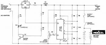
The Lithium Battery Charger circuit employs an LM317 voltage regulator, which is configured to provide a constant output current suitable for charging AA lithium cells. The design ensures that the charging current remains stable at 60 mA, which is optimal for maintaining battery health and efficiency during the charging process.
The circuit includes a diode to prevent reverse current flow, which could damage the power source or the battery being charged. A resistor is used to set the charging current, while a capacitor may be included for smoothing the output voltage and filtering any noise that could affect the charging performance.
The transistor in the circuit acts as a switch, which can be controlled to enable or disable the charging process based on the battery voltage levels. This feature is crucial for preventing overcharging, which can lead to battery degradation or failure. Once the voltage of the lithium cell reaches 2.4V, the circuit is designed to terminate the charge automatically, ensuring the safety and longevity of the battery.
The switch allows for manual control of the charging process, providing flexibility in operation. Overall, this circuit is an effective solution for safely charging lithium batteries while maintaining optimal performance through well-designed components and configurations.This circuit shows a Lithium Battery Charger circuit diagram. Charging is accomplished with a constant current of 60 mA for AA cells to a cutoff of 2. 4V per cell, at which point the charge must be terminated. Component: LM317 IC, Diode, Resistor, Capacitor, Transistor, Switch, Battery. [circuitdiagram. net] 🔗 External reference
Related Circuits
This circuit was specifically designed to recharge alkaline cells. The unusual connection of the transistor in each charging unit will cause it to oscillate, on and off, thus transferring the charge accumulated in the capacitor to the cell. The...
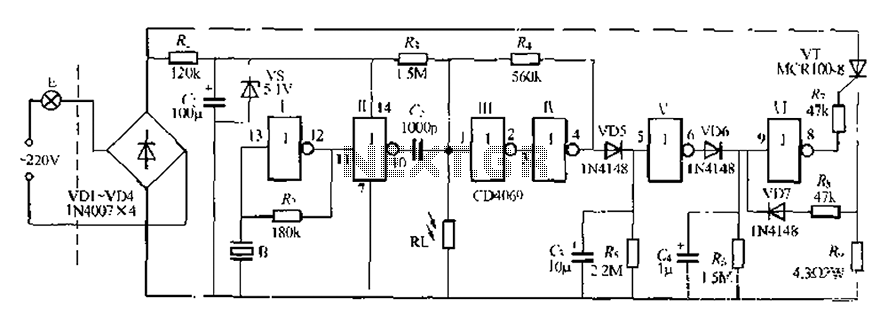
The circuit is designed for sound and light control of stairway and walkway lighting. It features high immunity and includes soft-start and over-current protection mechanisms. During the day, the photosensitive resistor has low resistance, resulting in a low voltage...
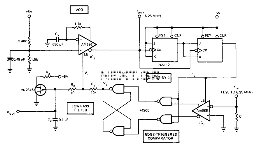
A circuit diagram of a phase-locked loop utilizes an AM686 latched comparator as a voltage-controlled oscillator, along with a TTL latch connected to generate edge-triggered comparators. The VCO and its comparison with the low-pass filter consisting of R1, R2,...
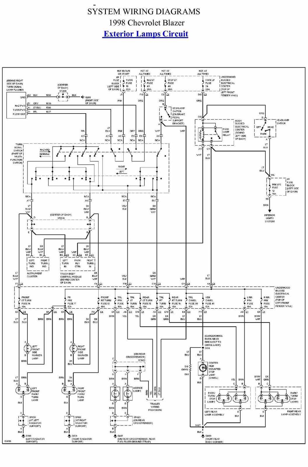
The schematic presented is the exterior lamp circuit diagram for the 1998 Chevrolet Blazer. The wiring diagram is straightforward and should be reviewed thoroughly prior to making any modifications to the vehicle's wiring connections. The components included in this...
This is an efficient four-stage stabilized power supply unit designed for testing electronic circuits. It delivers well-regulated and stabilized outputs, which are crucial for achieving accurate results in most electronic applications. The circuit features an audio-visual indication system that...

This is an automatic battery charger circuit that utilizes the LM324 integrated circuit, which enhances efficiency. It is capable of charging both 12V and 6V batteries, with filtration managed by switch S1. The circuit is designed to stop charging...