
Stablised Power Supply With Short-Circuit Indication
The design of this power supply unit is structured to ensure reliability and safety during operation. The use of a step-down transformer allows for efficient conversion of AC voltage to a lower DC voltage, which is necessary for powering various electronic devices. The inclusion of multiple output voltages enhances the versatility of the power supply, making it suitable for different testing scenarios.
The rectification process is facilitated by diodes D1 and D2, which convert the AC voltage to DC. Capacitor C1 plays a crucial role in smoothing the rectified voltage, minimizing ripples, and ensuring a stable output. The regulator ICs (IC1 to IC4) are critical components that maintain the output voltage at fixed levels, irrespective of variations in input voltage or load conditions. These ICs should be selected based on their current handling capabilities, ensuring they can adequately support the maximum load of 200mA.
Transistors T1 and T2 are used for switching and amplifying the output signal. Their complementary configuration allows for efficient control of the output voltage, and the presence of LED3 provides a visual confirmation of output availability, enhancing user interaction with the device.
The audio-visual indication system, comprising LED2 and the piezo-buzzer PZ1, is vital for immediate feedback on circuit conditions. This feature is particularly important during testing phases, as it alerts the user to potential issues, allowing for prompt corrective actions to prevent component damage.
The fuse-failure indicator, with its bicolor LED, serves as an essential safety feature, providing clear visual feedback regarding the operational status of the fuse. This allows users to quickly identify and address any issues that may arise during testing.
In conclusion, the design of this stabilized power supply unit emphasizes safety, versatility, and ease of use, making it an invaluable tool for electronics testing and development. Proper assembly on a PCB, along with effective heat management and enclosure considerations, will further enhance the performance and longevity of the circuit.Here is an efficient 4-stage stabilised power supply unit for testing electronic circuits. It provides well regulated and stabilised output, which is essential for most electronic circuits to give proper results. The circuit provides an audio-visual indication if there is a short circuit in the PCB under test, so the power supply to the circuit un
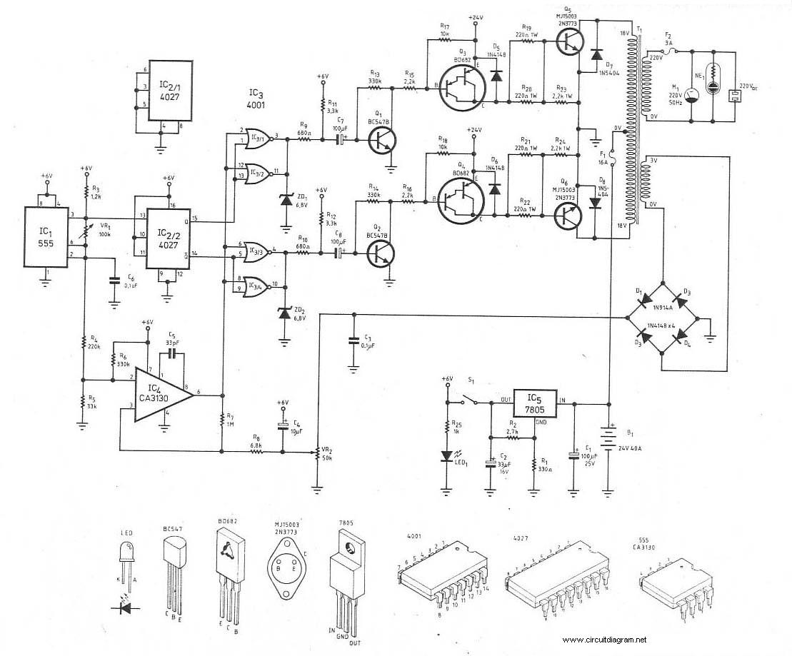
der test` can be cut-off immediately to save the valuable components from damage. The circuit provides four different regulated outputs (12V, 9V, 6V and 5V) and an unregulated 18V output, which are selectable through rotary switch S2. The selected output is indicated on the analogue voltmeter connected to the outputs rails. The circuit uses a standard 18V-0-18V, 500mA step-down transformer to generate 18V AC. A rectifier diode comprising diodes D1 and D2 provides 18V DC, which is smoothed by capacitor C1 and given to the combination of regulator ICs (IC1 through IC4).
The regulator ICs produce fixed, regulated outputs of 12V, 9V, 6V and 5V, respectively, which are connected to the rotary switch contacts. This power supply is useful for loads requiring up to 200mA current. Complementary transistors T1 and T2 conduct when the power to the circuit is switched on. Full selected supply voltage is available at the collector of transistor T2, which is used to power the load.
LED3 indicates the presence of output voltage. The negative terminal of piezo-buzzer PZ1 is connected to the output rail via LED2, so the piezo-buzzer remains silent as its negative terminal is also at full supply voltage (selected). If there is a short circuit at the output, LED2 glows to activate the piezo-buzzer. A fuse-failure indicator distinguishes short circuit at the output and input failure. It consists of a bicolour LED (LED1) and resistors R1 and R2. When power is available and the fuse is intact, red and green halves of LED1 are effectively in parallel to output a yellowish light.
When fuse fails, green LED goes off and red LED lights up to indicate fuse breakdown. The circuit can be easily constructed on a general-purpose PCB. Use small heat-sinks for all ICs to dissipate heat. The output voltage can be read on a voltmeter. Enclose the circuit in a metal box with provisions for voltmeter, LEDs, rotary switch, etc. 🔗 External reference
Related Circuits
The micropower circuit automatically provides shutdown, power-up, and low-battery lockout functions without requiring software or operator control. The micropower circuit is designed to manage power efficiently in battery-operated devices, ensuring optimal functionality while conserving energy. The shutdown feature is activated...

This circuit is commonly referred to as a Joule Thief, and it has been frequently encountered in various electronics videos on YouTube. The Joule Thief is a simple, low-cost circuit designed to extract energy from a single-cell battery, particularly when...
This is the schematic diagram of a 300W power inverter circuit. The inverter utilizes the MJ15003 power transistor for final amplification. If the MJ15003 transistor is difficult to source, it can be replaced with a 2N3773. The inverter is...

The low-cost and compact circuit presented here serves as a highly power-saving flashing LED indicator. While most LEDs typically fail to operate below 2 volts, with a forward voltage of at least 1.6 volts, this flasher can function using...
When the AC mains supply fails, this circuit triggers an alarm to alert the user. Additionally, it offers a backup light to assist in locating a flashlight or other emergency lighting. This circuit is designed to provide immediate notification and...

An interface circuit utilizing optocouplers provides galvanic isolation and common-mode noise rejection between low-voltage microcontroller units and high-voltage integrated power modules in motor-drive applications. Optocouplers ensure high-voltage isolation between a low-voltage device, such as a microcontroller or a pulse-width...