
Lithium charger
This project involves the design and implementation of a battery charging circuit specifically tailored for lithium-based batteries. The charging circuit is crucial for safely managing the charging process, ensuring that the batteries are charged efficiently without exceeding their maximum voltage limits, which can lead to battery damage or safety hazards.
The circuit typically incorporates a dedicated lithium battery charger IC, which is responsible for controlling the charging process. Commonly used ICs for this purpose include the TP4056 or the MCP73831. These ICs are designed to provide a constant current/constant voltage (CC/CV) charging profile, which is essential for lithium batteries.
The circuit configuration generally includes the following components:
1. **Power Source**: A micro USB connector or other suitable power input to provide the necessary voltage and current for charging. The input voltage should be in the range of 5V, which is standard for USB charging.
2. **Charger IC**: The selected charger IC should be connected to the power source and the lithium battery. The IC will manage the charging cycle, ensuring that the battery receives the correct voltage and current.
3. **Current Limiting Resistor**: A resistor may be included in series with the battery to limit the charging current, protecting the battery from excessive current flow.
4. **Protection Circuitry**: It is advisable to include over-voltage, over-current, and thermal protection circuits. These may consist of MOSFETs, fuses, or dedicated protection ICs, which will disconnect the battery from the circuit in case of unsafe conditions.
5. **LED Indicators**: Optional LED indicators can be integrated to provide visual feedback on the charging status. Typically, a red LED may indicate charging, while a green LED signifies that the battery is fully charged.
6. **Capacitors**: Bypass capacitors are often placed near the power input and the charger IC to filter out noise and stabilize the voltage levels.
The layout of the circuit should be designed to minimize the length of the connections to reduce resistance and inductance, which can affect charging performance. Proper thermal management should also be considered, as the charger IC may generate heat during operation.
Overall, this project serves as a practical solution for charging lithium-based batteries safely and effectively, making it an invaluable addition to any electronics toolkit.You will need this project when you have an extra mobile battery or you need to charge any lithium, Lithium ion or Lithium Polymer battery. Maximum c.. 🔗 External reference
Related Circuits
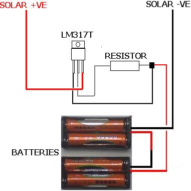
The following circuit illustrates the LM317T IC designed for a solar battery charger circuit diagram. Features include a simple circuit suitable for AA and AAA rechargeable batteries. The LM317T is a versatile linear voltage regulator that can be used in...
This simple charger utilizes a single transistor as a constant current source. The voltage across the pair of 1N4148 diodes biases the base of the BD140 medium power transistor. The circuit operates by employing the BD140 transistor to regulate the charging...
This project is one for the experimenter, but as shown will work extremely well. The sensing circuit can be made so sensitive that a load of only 2.5mA is enough for the circuit to detect, and disconnect the charger....
This charger is designed to quickly and efficiently charge most lead-acid batteries. It is an electronics project that is easy to construct, and a circuit diagram is included. The lead-acid battery charger circuit typically consists of several key components that...
This circuit serves a function for digital cameras. It is well-known that digital cameras have considerable power consumption. The circuit is designed to optimize power management for digital cameras, addressing the challenge of high energy usage during operation. It...
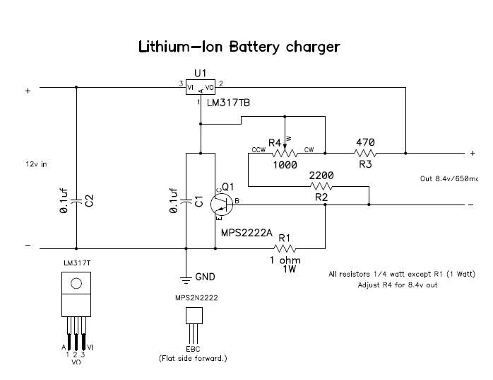
This circuit was built to charge two series lithium cells (3.6 volts each, 1 Amp Hour capacity) installed in a portable transistor radio. The circuit is designed to efficiently charge two lithium-ion cells connected in series. Each cell has a...