
Lithium Ion Lithium Poly Charger by LM317
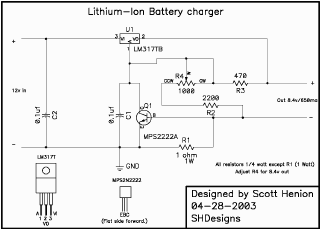
The circuit described is a simple yet effective Li-Ion battery charger for 2-cell configurations. The charging process is initiated by applying a voltage from an external power source, which can be either a 12V gel cell battery or a DC wall transformer, ensuring that the current does not exceed the specified maximum of 650mA. This design is particularly beneficial for applications requiring a reliable and straightforward charging solution for Li-Ion batteries with a capacity of 900mAh or greater.
The circuit typically incorporates a charging controller IC that regulates the charging current and voltage to prevent overcharging, which is critical for maintaining the health and longevity of Li-Ion batteries. The components may include resistors for current limiting, capacitors for smoothing the voltage output, and possibly diodes for reverse polarity protection.
The power supply used in this circuit does not need to be regulated, allowing for some flexibility in sourcing the input voltage. However, it is essential to ensure that the power supply can deliver sufficient current without causing voltage spikes that could damage the battery or the circuit. The mention of a 12V/1A adapter indicates that the circuit can handle variations in input voltage, which is advantageous in practical applications.
Overall, this circuit provides a practical solution for charging 2-cell Li-Ion battery packs, making it suitable for various electronic projects and devices that require reliable battery management. Proper attention to component selection and circuit design will enhance performance and safety during operation.The above circuit will charge any 2-cell * Li-Ion battery pack. Maximum current is about 650 milliamps. The circuit is designed for batteries of 900mah or higher. Note this circuit is NOT for Li-Metal batts (i. e. Duralites). Power source can be a 12v Gell cell (Power panel), or can be powered by a car`s cigarette lighter. I use an old 12v DC wall transformer (800ma or more. ) Radio shack sells a 12v/1amp wall DC adapter #273-1776 that will work. Supply does not need to be regulated. In fact my cheap supply outputs 17 volts with no load. Disclaimer All files are found using legitimate search engine techniques. This site does not and will not condone hacking into sites to create the links it list. We will and do assume that all links found on the search engines we use are obtained in a legal manner and the webmasters are aware of the links listed on the search engines. If you find a URL that belongs to you, and you did not realize that it was "open to the public", please use the report button to notify the blogmaster of your request to remove it or it will remove within 24 hours.
This is not an invitation for webblog haters to spam with requests to remove content they feel that is objectionable and or unacceptable. Proof of URL ownership is required. NOTICE: This Blog Has Already Been Reviewed And Accepted By Blogger. com 🔗 External reference
Related Circuits
The information apparatus includes a buck rectifier power supply providing Vdd at +12V, a timing circuit, a multivibrator, and the output from the first amplifier. The components R1, RP1, and C3 are used to initiate timing, with the timing...
A high brightness LED evaluation board has been developed using the Fairchild Semiconductor FAN7554D PWM controller. The evaluation board for high brightness LEDs incorporates the Fairchild Semiconductor FAN7554D PWM controller, which is designed to provide efficient power management and precise...
IC4 serves as a counter and oscillator combination, which is the pivotal component of the circuit. The oscillator generates an AC signal that is output on pin 7. This signal is routed through a voltage divider composed of resistors...
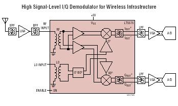
The LT5575 is an 800MHz to 2.7GHz direct conversion quadrature demodulator optimized for high linearity receiver applications. It is suitable for communications receivers where an RF signal is directly converted into I and Q baseband signals with a bandwidth...
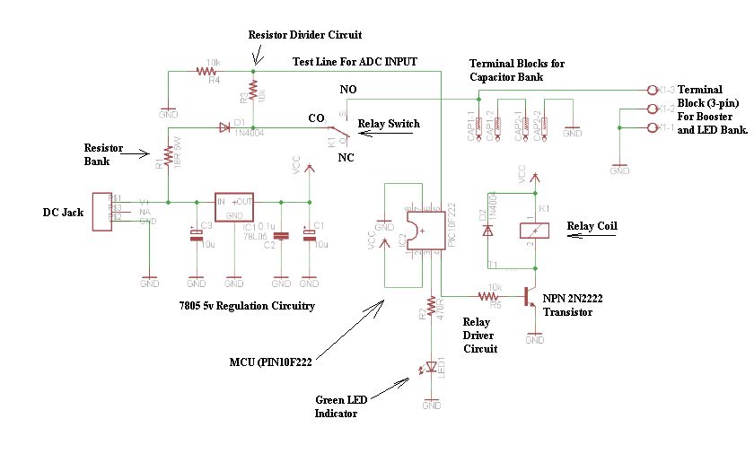
The schematic consists of four hardware blocks: 1) The wall transformer 2) The charging circuit 3) The control unit 4) The output stage. The circuit schematic is structured around four essential hardware blocks that facilitate the overall functionality of the...
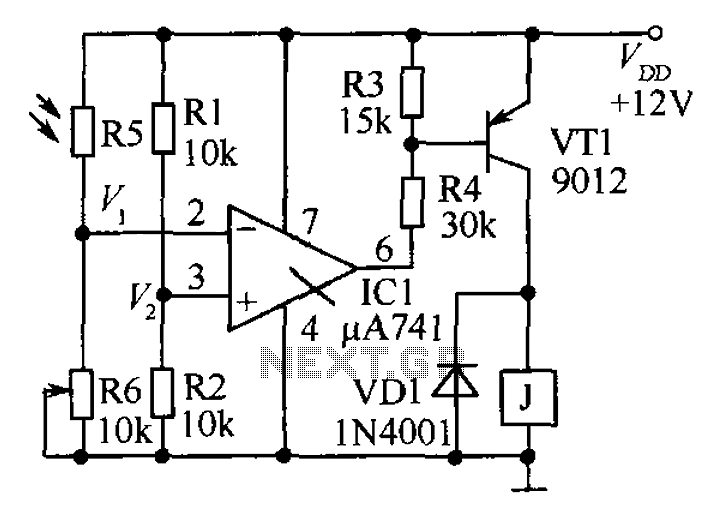
The circuit functions as a precision bright light control circuit, operating independently of power supply voltage and ambient temperature. Resistors R1, R2, R6, and the photosensitive resistor R5 form a two-arm Wheatstone bridge. The precision bright light control circuit utilizes...