
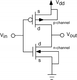
The basic form of frequency equalization circuit
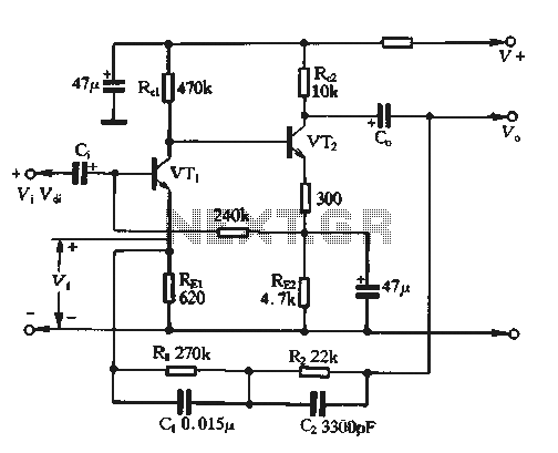
The circuit described involves a feedback mechanism that utilizes the EQ network to stabilize the output voltage by adjusting the input voltage. The feedback voltage (Vf) is critical in controlling the gain of the system, which is represented by the coefficient B. This coefficient is a ratio of the feedback voltage to the output voltage, indicating the effectiveness of the feedback loop in maintaining desired performance characteristics.
The equation B = Vf / Vo illustrates the relationship between the output voltage and the feedback voltage, where REI denotes the resistance in the feedback path, Zm represents a load impedance, and REIo is an additional resistance that contributes to the feedback loop. The total frequency characteristic impedance (ZEQ) of the balanced network plays a significant role in determining the frequency response of the circuit, impacting how the circuit behaves under varying signal conditions.
When the circuit operates without negative feedback, the feedback voltage (Vf) is zero, indicating that the circuit is in an open-loop configuration. In this state, the input voltage (vi) is maintained at a specific level, which allows for an assessment of the circuit's natural gain. The voltage magnification, expressed as V = Vo / Vdi, provides insights into the amplification capabilities of the circuit, highlighting the importance of feedback in achieving stable and predictable performance.
In summary, the circuit's feedback mechanism, characterized by the EQ network and the associated equations, is essential for optimizing voltage control and enhancing the overall functionality of the electronic system. The interplay between the feedback voltage, output voltage, and various resistances defines the operational dynamics of the circuit, ensuring effective performance across different conditions.The figure for the feedback voltage Vf, it is taken from the output voltage Vo by EQ network. Input voltage Vf i and subtraction to give pure input voltage of the circuit belongs Vdjo tandem type negative voltage feedback coefficient B Vf / Vo = REI / Zm + REIo where ZEQ total frequency characteristic impedance balanced network. When the circuit without negative feedback, Vf = OV, V & vi = 'At this point the voltage magnification V- Vo / Vdi.
Related Circuits
An AC to DC circuit converts sinusoidal alternating current into direct current. If the input signal is not sinusoidal, such as a triangular wave, the distortion is significant. The relationship between the average value and the RMS value is...

An audio power amplifier circuit for a 3-watt stereo amplifier using the MAX 7910 IC is explained below. The audio power amplifier circuit utilizing the MAX 7910 IC is designed to deliver a maximum output power of 3 watts per...
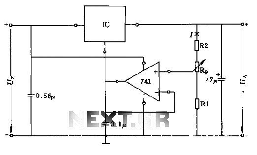
The circuit consists of resistors R1, R2, and RP, where the resistance values play a critical role in determining the magnitude of the current I. This current must exceed the input current of the operational amplifier, which is approximately...
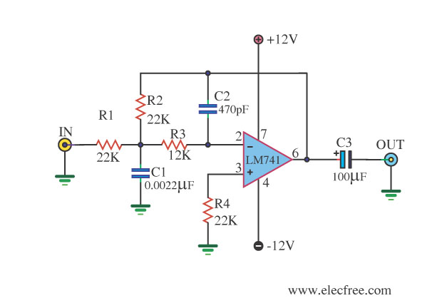
This circuit filters low frequencies below 10 kHz using the highly popular operational amplifier IC uA741. It is convenient for applications that require the conversion of analog signals to digital or vice versa. In digital sound systems, this circuit...
The fundamental issue presented is the perception that logic gates in a circuit seem to generate power from nothing, which contradicts the principles of physics. For instance, consider two NOT gates connected in series. It appears that the first...
Crystal 80mW FM transmitter circuit diagram of the production The Crystal 80mW FM transmitter circuit is designed to generate frequency modulated (FM) signals suitable for short-range audio transmission. This circuit primarily consists of a crystal oscillator, which serves as...