
LM1201 Video Amplifier with Balanced (Bi-Phase) Output
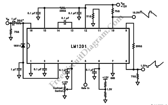
The video amplifier circuit employs the LM1201 integrated circuit, which is specifically designed for video processing applications. The bi-phase output feature is crucial for applications requiring differential signaling, which enhances noise immunity and allows for longer transmission distances.
The circuit operates by taking an input video signal and amplifying it while ensuring that both the positive and negative phases are produced. The termination resistor of 75 ohms at pin 10 is essential for impedance matching, minimizing signal reflections, and ensuring optimal signal integrity.
The voltage divider connected to pin 6 plays a significant role in setting the black level of the video signal. By adjusting the voltage at this pin, the circuit can maintain a consistent reference level for the inverted video output at pin 8, which is critical for accurate video representation. The output at pin 8 is expected to be a clean and stable inverted video signal, which can then be further processed or transmitted as needed.
Overall, this schematic diagram illustrates a robust video amplifier circuit that effectively handles video signals with precision, making it suitable for various applications in video processing and transmission systems.This is a schematic diagram of video amplifier circuit with bi-phase output. Bi-phase output provides both positive-going and negative-going signal, and can be used as balanced signaling. The main component of this circuit is LM1201 In this circuit, the inverted video is obtained at pin 10 because of the 75 © termination to the power supply vo
ltage. The voltage divider on pin 6 is used to set the black level on inverted video (pin 8) to 1. 5V. Here is the schematic diagram of the circuit: 🔗 External reference
Related Circuits
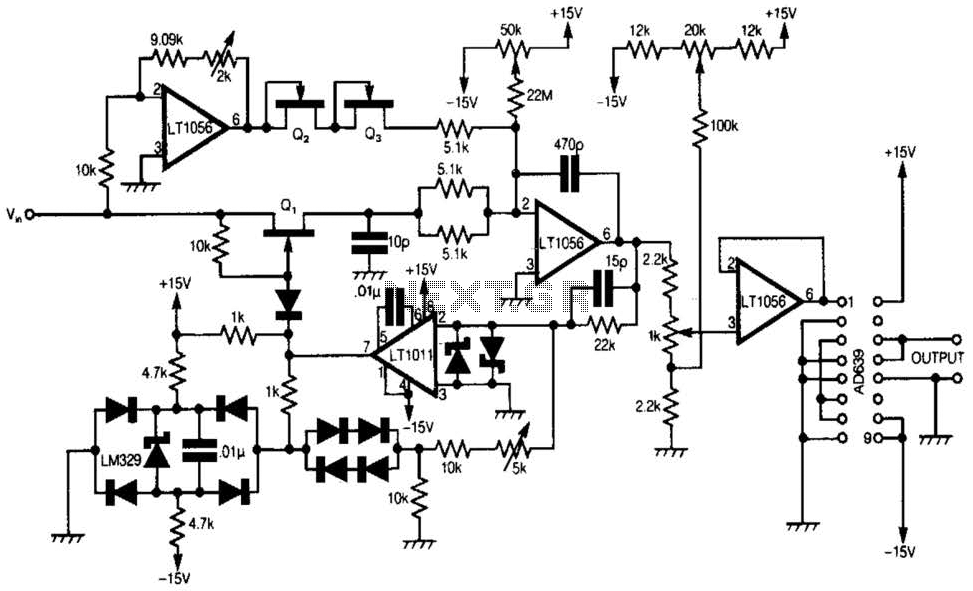
A 555 timer and a dual 556 timer are used to generate a basic video signal, as illustrated in the schematic. The first timer operates in astable mode, producing synchronization pulses with a period ranging from 4.7 to 8...
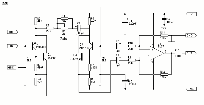
The design consists of differential compound pairs of transistors with a common mode (floating) gain control connecting the emitters of the pair. The compound pairs of 2N4403 and BC549s are far more linear than any single transistor. The circuit...
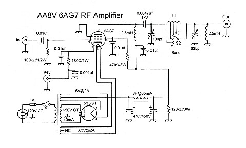
The input coupling capacitor allows the input signal to pass through to the grid of the tube while preventing the input source from potentially shorting the grid bias to ground. If the grid bias were shorted out, the 6AG7...
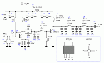
An RF power amplifier is a type of electronic amplifier used to convert a low-power radio-frequency signal into a larger signal of significant power, typically for driving the antenna of a transmitter. It is optimized for high efficiency, high...
This document discusses the advantages and disadvantages of various power supply technologies, along with the design considerations necessary for selecting and evaluating a mains transformer. It covers the pros and cons of external supplies, inrush current control, RF emissions...
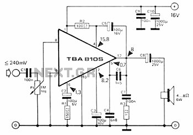
This circuit is a 7 Watt audio amplifier that is simple and easy to construct. It utilizes the TBA810 as the primary component, supported by a few passive components. The amplifier operates effectively, and the necessary kits and components...