
Arduino Motion Sensor
To implement motion sensing capabilities with an Arduino board, a typical circuit would involve the integration of a passive infrared (PIR) sensor, which is commonly used for detecting motion. The PIR sensor operates by detecting changes in infrared radiation levels emitted by objects in its field of view, primarily human bodies.
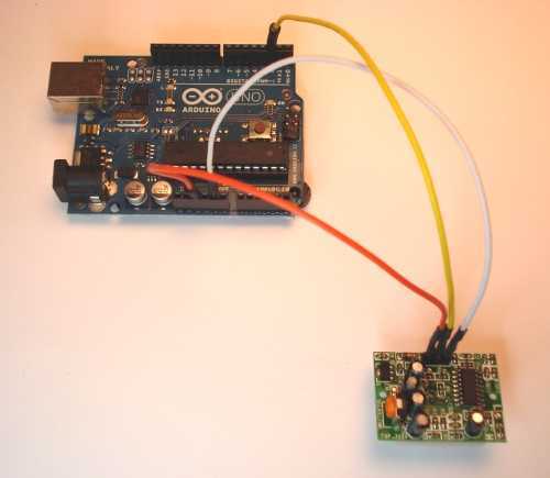
The circuit design begins with connecting the PIR sensor to the Arduino board. The sensor typically has three pins: VCC (power), GND (ground), and OUT (output). The VCC pin should be connected to the 5V output of the Arduino, while the GND pin connects to the ground. The OUT pin is connected to a digital input pin on the Arduino, which will read the motion detection signal.
For the Arduino programming, the code should be structured to continuously monitor the state of the OUT pin. When motion is detected, the pin will output a HIGH signal, which can be used to trigger various responses, such as turning on an LED, activating a buzzer, or sending a notification via a connected module (e.g., Wi-Fi or Bluetooth).
Additionally, it is essential to consider the power supply requirements and ensure that the Arduino board is adequately powered, especially if additional components are added to the circuit. A breadboard can be useful for prototyping, allowing for easy modifications and testing of the circuit.
In summary, by utilizing a PIR sensor in conjunction with an Arduino board, one can create an effective motion sensing system that can be adapted for various applications, such as security systems, automated lighting, or interactive installations.Give your Adruino board a motion sense around it! Use any Arduino board: Uno, Mega, Duemilanove etc. 🔗 External reference
Related Circuits
The MAXQ3210 is a powerful RISC microcontroller. This device has features and capabilities that make it suitable for battery-powered applications that require detection. The MAXQ3210 microcontroller is designed with a focus on low power consumption and efficiency, making it particularly...
A project involving a moisture sensor alarm circuit designed to detect moisture levels in plant soil, wood, and irrigation areas. The moisture sensor alarm circuit typically consists of a moisture sensor, a microcontroller or comparator circuit, an alarm system, and...
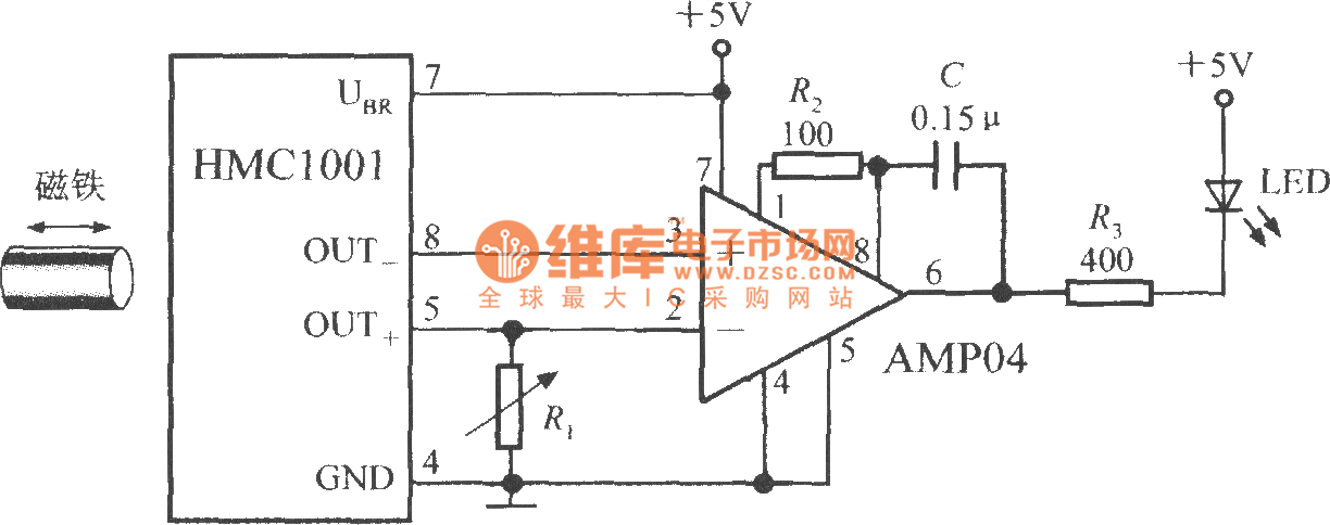
The proximity switch circuit consists of the HMC1001 sensor, operational amplifier (AMP04), and a light-emitting diode (LED). The operational amplifier functions as a comparator. When a magnet, measuring between 6mm and 12mm, is moved to a predetermined position near...
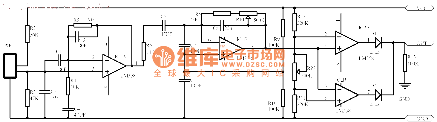
Passive human body infrared sensor circuits are generally similar in design, although some may have fewer stages. The circuit illustrated is sourced from the NICERA manufacturer and is considered a classic example. The front-end stage consists of a low-frequency...
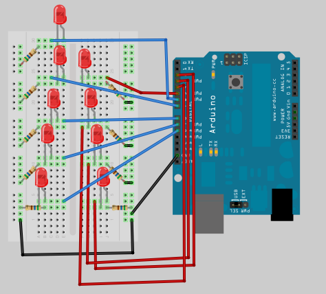
This is the next part in the Arduino learning series, focusing on the use of arrays to create a small Christmas tree ornament with various flashing sequences. This project is suitable for engaging children in basic soldering skills—simply mount...
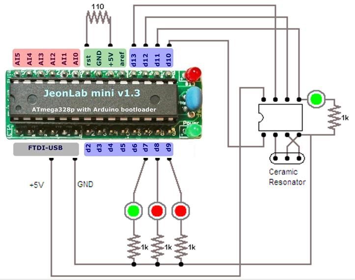
For relatively small projects with fewer pins than the ATmega328, the ATtiny series, specifically the ATtiny45 or ATtiny85, is a good choice due to its compact physical size. The ATtiny series microcontrollers, particularly the ATtiny45 and ATtiny85, are designed for...