
Adjustable dual voltage power supply circuit
The adjustable dual voltage power supply circuit is designed to provide a versatile power source for various experimental applications. It features two adjustable voltage outputs that can be independently set within a range of 1.5V to 25V, making it suitable for a wide array of electronic components and circuits requiring different voltage levels.
The heart of this power supply is the three-terminal voltage regulator integrated circuits (ICs), specifically the 78 series, which are known for their reliability and ease of use. The use of N1 and N2 circuits ensures that the power supply can deliver both positive and negative voltages, which is essential for many electronic experiments.
The transformer T is a crucial component, as it steps down the AC voltage from the mains supply to a lower AC voltage suitable for rectification. The VD rectifier converts the AC voltage into DC, while the C4 capacitor acts as a filter, smoothing out the rectified voltage to reduce ripple. This ensures a stable DC output which is vital for maintaining the performance of sensitive electronic components.
Voltage regulation is achieved through the VS regulator, which maintains the output voltage at the desired level despite variations in load current. The Yan component limits the maximum voltage to protect downstream components from overvoltage conditions.
The circuit includes switches S1 and S2, allowing the user to select the desired polarity for the output voltage, which enhances the flexibility of the power supply. The adjustment potentiometers RP1 and RP2 enable fine-tuning of the output voltages, allowing for precise control based on the requirements of the experiment.
Thermal management is a critical aspect of this design. When the output voltage is significantly lower than the input voltage, the voltage drop across the regulators increases, leading to higher power dissipation. This necessitates the use of heat sinks to prevent overheating and ensure the longevity of the integrated circuits.
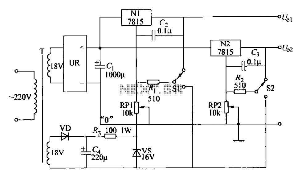
In conclusion, this adjustable dual voltage power supply circuit is a well-engineered solution for providing variable voltage outputs in a laboratory setting, with careful consideration given to voltage regulation, thermal management, and user flexibility.Adjustable dual voltage power supply lines shown, can be used as a power supply line frequently used experiments. Its current does not exceed 1A, but two voltages are adjustabl e, and each other. Nl, N2 and 78 series three-terminal voltage regulator integrated circuit, since the output voltage is equal to the nominal value of the common voltage ground voltage and therefore to the common terminal coupled with a long adjustable positive and negative voltages, you can make output voltage level is adjustable. The line N1, N2 share a rectifier power supply. Transformer T is another set of output, the VD rectifier, C4 filter wave, Yan limiting, VS regulator, dedicated to providing a total negative reference voltage through the switch Sl, S2 selectable power-on the common side of the polarity voltage, and then adjust RP1 or RP2, it can be adjusted separately two output voltages.
According to the data shown, the two output voltage can be continuously variable within 1. 5-25V range, voltage stability also meet the requirements. When the voltage is lowered, the integrated circuit input/output voltage difference is large, a corresponding increase in power consumption, it is necessary to install the heat sink. In addition, when selecting positive reference voltage, potentiometer wiper closer to the end, the higher the output voltage, and the choice of a negative reference voltage, the slide arm close to the low output voltage.
Select principle RP1, RP2 is to make voltage value is slightly higher than the nominal value of the integrated circuit is appropriate. Input voltage regulator circuit/output voltage difference between the maximum generally not more than 35V, therefore, should not be higher than the transformer secondary voltage 25V, to avoid damage to the integrated circuit.
Related Circuits
In the production of LCD projectors, the primary factor threatening the lifespan of the LCD screen is the temperature generated by halogen lamps. The multi-function controller designed by this circuit is highly effective for protecting liquid crystal projectors. The...
This area illustrates the construction and testing of a new half-wave (dual) Tesla coil. This type of coil features two secondaries driven by a single tank circuit. The design presented is a small and relatively inefficient dual coil constructed...
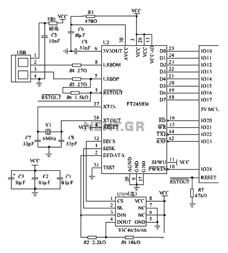
The FT245BM typical hardware circuit operates in bus-powered mode and employs a power-on reset mechanism to initialize the device. The clock circuit can be implemented using a 6 MHz crystal oscillator module or a combination of a 6 MHz...
The digital scoreboard circuit is designed to display numerical values ranging from 0 to 9 on a common anode 7-segment display. The circuit employs a 7-segment driver integrated circuit (IC), specifically the 74LS47 or 74LS247. A 555 timer IC...
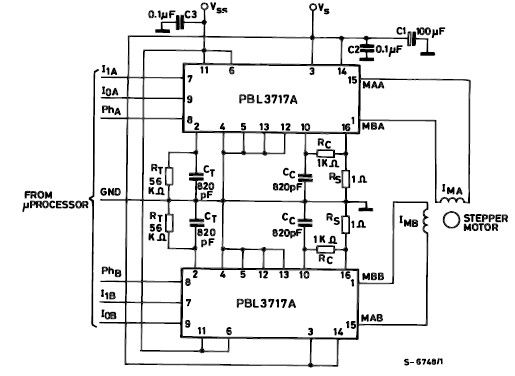
The PBL3717A stepper motor driver is a monolithic integrated circuit that controls and drives one phase of a bipolar stepper motor utilizing chopper control for phase current regulation. Current levels can be selected in three increments using two logic...
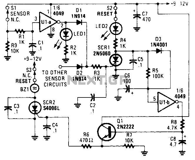
The alarm/sensor circuit is constructed using two SCRs, a transistor, a 4049 hex inverter, and several supporting components, which together create a closed-loop detection circuit featuring a delay mechanism. This delay allows entry into a protected area and deactivation...