
Toy Train rail detector circuit II
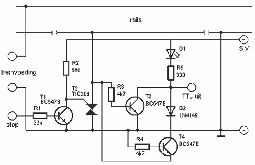
More: R1 = 22 kOhm Because two transistors and two diodes are used, the circuit works in both directions. When the stop input a high signal is presented, the gate of the triac is shorted to ground. The line will be energized. This can be used as an emergency stop. R2 = 560 ? R3, R4 = 4.7 kOhm R5 = 330 ? D3 = LED D4 = 1N4148 T1, T3, T4 = BC 547B T2 = 206 TIC
This circuit is designed to detect the presence of a train on a specified track section and provide an output that is compatible with TTL and CMOS logic levels, making it suitable for integration with various computer systems. The core components include a triac (T1), which serves as a switching device, and several transistors (T3, T4) that amplify the signal for output processing.
The circuit operates by connecting a driving voltage to two terminals. When a train interrupts the line, the current flows through the triac T1, generating a voltage of approximately 1V. This voltage is sufficient to turn on the transistors T3 and T4, which in turn illuminate the LED (D1), indicating the detection of the train. The output state during this condition is logical zero, which is a common signal used in digital circuits.
Resistor R1, valued at 22 kOhm, plays a crucial role in limiting current within the circuit, ensuring that the transistors operate within safe parameters. The circuit's design allows for bidirectional operation due to the inclusion of two transistors and two diodes, enhancing its functionality.
In scenarios where an emergency stop is required, the circuit can respond to a high signal at the stop input. This signal shorts the gate of the triac to ground, effectively energizing the line and ensuring that the train can be halted safely.
Additional components include resistors R2 (560 Ohm), R3, and R4 (both 4.7 kOhm), and R5 (330 Ohm), which are used to set biasing and current limiting for the transistors and LEDs. The diodes D3 (LED) and D4 (1N4148) are included for signal indication and protection against reverse polarity, respectively.
The transistors used in this circuit are BC 547B for T1, T3, and T4, which are general-purpose NPN transistors suitable for low-power switching applications. The triac T2 is a 206 TIC, which is utilized for its ability to control AC loads, providing versatility in controlling train operations.This circuit can detect whether a train in a particular drive. The output is TTL and CMOS compatible and can be processed by such a computer. The simple circuit works. The driving voltage is connected to the two terminals left. When the locomotive of the interrupted line is, the flow leading to the locomotive goes through the triac T1. This is then a voltage of about 1 V, which is conducting T3 or T4. Therefore, the LED D1 on and the output is logical zero. R1 = 22 kOhm Because two transistors and two diodes are used, the circuit works in both directions. When the stop input a high signal is presented, the gate of the triac shorted to ground. The line will be energized. This can be used as an emergency stop. R2 = 560 ? R3, R4 = 4.7 kOhm R5 = 330 ? D3 = LED D4 = 1N4148 T1, T3, T4 = BC 547B T2 = 206 TIC 🔗 External reference
Related Circuits

One of the backup systems utilizes a Magnum MS-PAE 4024 inverter, which lacks a built-in fan controller. Since batteries emit hydrogen during both normal and equalization charging, it is crucial to ventilate the batteries to the outside using a...

A capacitive proximity controller typically consists of a radio frequency oscillation circuit and a detection plate. The circuit is constructed using discrete components for capacitive proximity sensing detection. The transistor VT1, along with surrounding components, forms a radio frequency...

This Lazy Old Geek is also an Arduino enthusiast. One of the common microcontrollers used by Arduinos is the Atmega328 chip. To utilize Arduino software, the Atmega must be equipped with bootloader software. There is a notable difference between...

This shadow alarm circuit can detect a moving shadow in a confined area, providing protection against theft. When an individual approaches the unit, it triggers a loud alarm to deter the theft attempt. The circuit leverages the light-sensing characteristics...

The 741 operational amplifier can function as a voltage comparator. It features a non-inverting input and a Zener-controlled voltage source, with a reference voltage set at 5.1V. Resistor R2 is used to adjust the in-phase input voltage to half...
A ceramic resonator can be utilized to construct an oscillator. A single digital inverter can be employed to create a Pierce oscillator. To design a Pierce oscillator using a ceramic resonator and a digital inverter, the following components and configurations...