
Sensitive Triac Controller Circuit
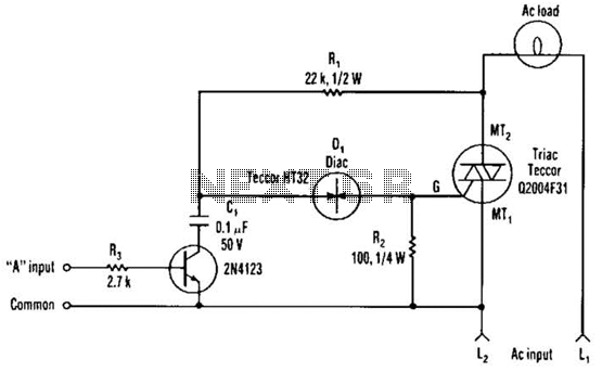
The described circuit utilizes a single transistor as a control element, interfacing a low-voltage logic signal with a TRIAC, which is capable of handling higher power applications. The transistor is positioned between a capacitor and the common side of the AC line, effectively allowing the logic-level signal to initiate the TRIAC's conduction state. This configuration is particularly useful in applications where microcontrollers or other digital logic devices need to control AC loads.
The capacitor serves as a timing element that, when charged, can influence the base of the transistor. When the logic signal is applied, it turns the transistor on, allowing current to flow and subsequently triggering the TRIAC to conduct. The TRIAC remains in the 'on' state until the current through it drops below a certain threshold, thereby allowing it to control AC power to the load.
Resistor R2 plays a crucial role in ensuring the stability of the circuit by preventing false triggering of the TRIAC. It limits the trickle current that can flow through the DIAC, which is a device that typically requires a certain threshold voltage to turn on. Without R2, even small fluctuations in the circuit could inadvertently trigger the TRIAC, leading to unwanted operation of the connected load. By carefully selecting the value of R2, the circuit designer can ensure that only intentional signals from the logic device will activate the TRIAC, thus enhancing the reliability and performance of the overall system.
This configuration is widely used in applications such as light dimmers, motor speed controls, and other AC power control scenarios, where precise control over the load is necessary while maintaining the integrity of the low-voltage control signal. The single transistor connected between the capacitor and the common side of the ac line allows a logic-level signal to control this triac power circuit. Resistor R2 prevents false triggering of the triac by the trickle current through the diac. 🔗 External reference
Related Circuits
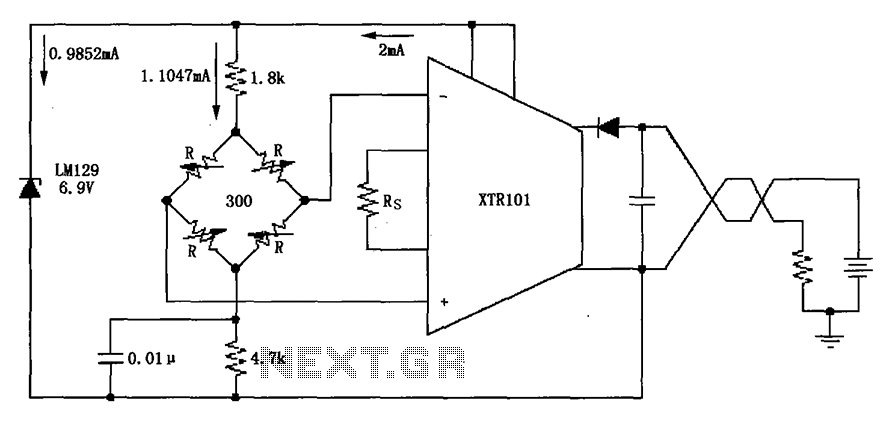
The circuit utilizes the LM129 voltage regulator to produce a 6.9V voltage reference, supplying a current of 1.0147mA from the 6.9V reference voltage to the bridge. The bridge may consist of varistor-type pressure sensors. The LM129 voltage regulator is a...
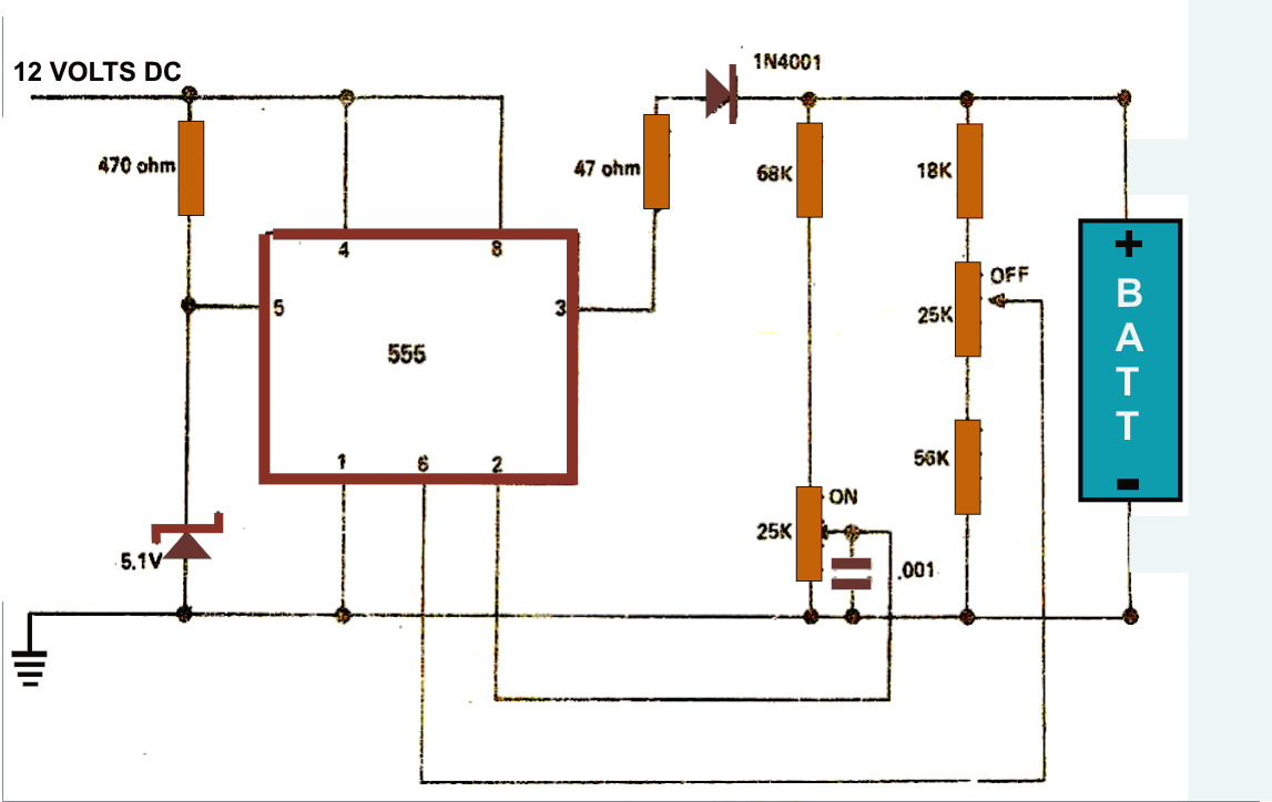
The simple battery charger circuit design presented here utilizes the versatile IC 555 as its primary component. This circuit is capable of charging various types of rechargeable batteries within the specified limits outlined in the article. The battery charger circuit...
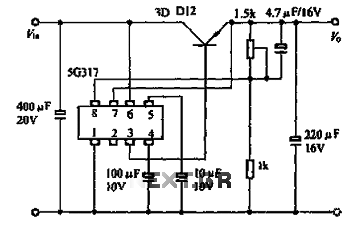
The 5G317 is an integrated voltage regulator circuit used in wiring applications for televisions. The maximum input voltage for the 5G317 should be less than 25V, while the output voltage ranges from 10V to 18V. The maximum output current,...
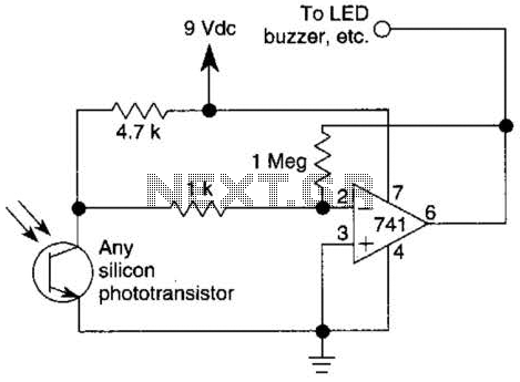
This circuit represents one of the simplest infrared (IR) receivers that can be constructed. The components are inexpensive, the layout is not critical, and a 9-V battery provides a long operational life. The described IR receiver circuit typically consists of...
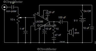
This is a simple low-power audio amplifier circuit capable of producing a power output of 1W. The mono amplifier circuit is built around the LM386 integrated circuit, which operates effectively at low voltages, even below 9V. This low-voltage amplifier...
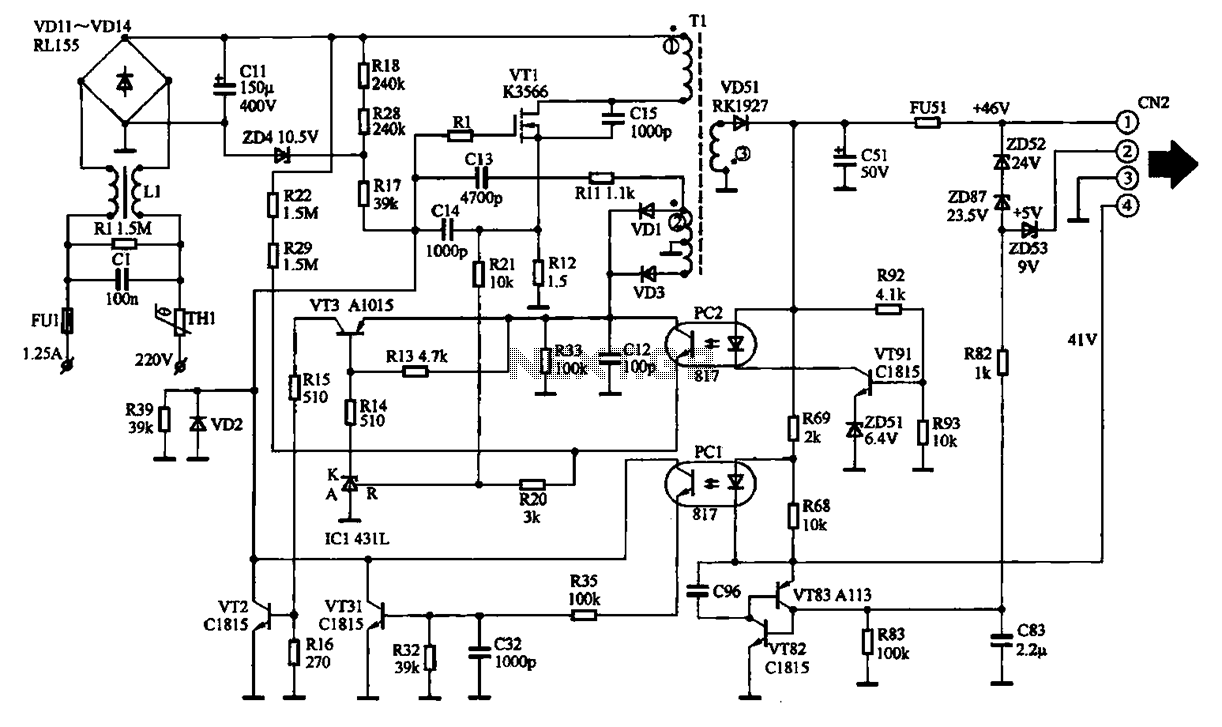
The EPSON PHOTO 830U printer power circuit illustrates the power supply circuit for the EPSON PHOTO 830U printer, which operates as a switching power supply. During normal operation, the power supply input socket receives a 220V AC supply to...