
Motor speed controller with timer 555
Pulse Width Modulation (PWM) is a widely used technique in electronics for controlling the power delivered to electrical devices. The fundamental principle involves varying the duty cycle of a square wave signal, allowing for precise control over analog devices such as motors and lights. In a typical PWM circuit, a square wave is generated with a frequency that can be adjusted according to the application requirements. The width of the pulse within this wave is modulated, which effectively changes the average voltage and current supplied to the load.
In a dimmer circuit, for instance, the PWM signal is employed to adjust the brightness of a light source. By varying the pulse width from 5% to 95%, the circuit can achieve a range of light intensities. At a 5% duty cycle, the light appears dimmed significantly, while at a 95% duty cycle, it operates at full brightness. Similarly, in motor speed control applications, the PWM signal regulates the motor’s speed by altering the power delivered to it. A low duty cycle (5%) results in low speed, while a high duty cycle (95%) allows the motor to reach its maximum speed.
The circuit components required for constructing a basic PWM controller include a 1kΩ resistor, a 1mF tantalum capacitor, two 1N4148 diodes, a 100kΩ variable resistor, and a 555 timer IC. The 555 timer operates in astable mode to generate the PWM signal. The variable resistor allows for manual adjustment of the duty cycle, enabling users to fine-tune the output as needed.
The use of diodes in the circuit serves to protect against reverse voltage and enhance the performance of the PWM signal. Additionally, the choice of capacitor can influence the circuit's filtering capabilities, which is crucial for minimizing radio frequency interference (RFI) that may arise from the rapid switching of the PWM signal. In some cases, replacing the tantalum capacitor with a different type may help reduce RFI further.
In summary, PWM is a versatile method for controlling power in electronic circuits, with applications ranging from lighting to motor control. The careful selection of components and attention to circuit design can optimize performance and mitigate potential issues such as interference.Pulse width modulation (PWM) is a technique to control analog circuits with a digital output. PWM is used in many applications, Specially to control light intensity and speed on motors. A PWM circuit makes a square wave with a variable width. The pulse width in this circuit can be varied from 5% to 95%. Used in a dimmer, this circuit controls the light intensity according the pulse width. On speed controller, the power of the motor depends the width from 5% (low power/speed) to 95% (full power/speed). The main disadvantage of this circuit, as all PWM circuits, is the possibility of generating radio frequency interference (RFI).
It can be reduced changing the capacitor.
Parts needed: * 1 1k Resistor * 1 1mF Capacitor (Tantalium capacitors works great) * 2 4148 Diodes * 1 100k Variable resistor * 1 IC 555 oscillator. Germanium diodes can be used to increase the range of the PMW up to 1% to 99%.
🔗 External referenceRelated Circuits
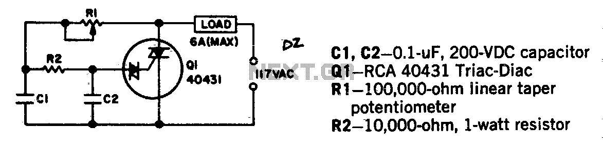
Universal motors and shaded-pole induction motors can be effectively controlled using a full-wave Triac speed controller. Component Q1 integrates both the Triac and diac trigger diodes within a single package. The motor employed for the load should not exceed...
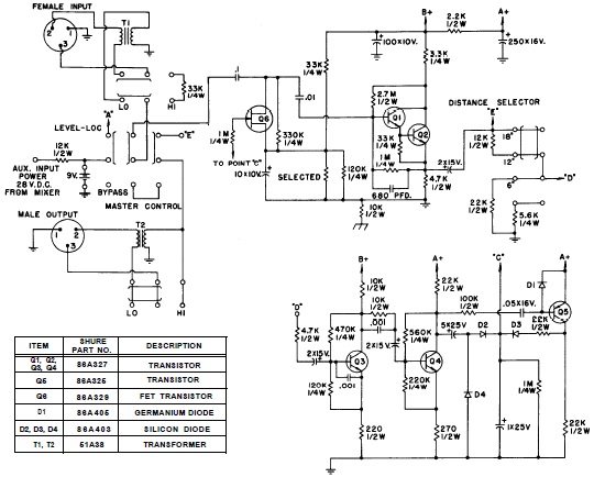
SHURE is an American corporation that manufactures consumer and professional audio electronics, including microphones, phonograph cartridges, and discussion systems. SHURE Incorporated is a well-established entity in the audio electronics industry, recognized for its innovative design and high-quality products. The company...
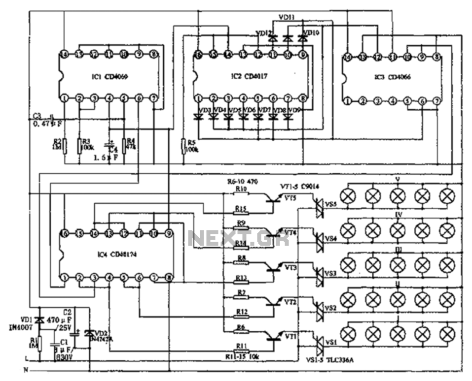
The circuit primarily consists of the NAND gate IC1 (CD4096), a counting/timing distribution circuit IC2 (CD4017), an analog electronic switch IC3 (CD4066), and a D flip-flop IC4 (CD40174), along with other components. The controller is capable of managing the...
The circuit is a bell timer. This project utilizes the AT89S52 microcontroller and an I2C EEPROM for storing alarm timings. Additionally, the 7-segment display has been replaced with an LCD display. The DS1307 is employed for real-time clock functionality....
This circuit provides a visual 9-second delay using a 7-segment digital readout LED. When the switch is closed, the CD4010 up/down counter is preset to 9, and the 555 timer is disabled with the output held high. The circuit utilizes...
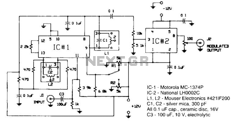
Circuit for applying a DC-coupled FM or PPM to a 555 configured as an oscillator. IC-1 is a Motorola MC-1374P, and IC-2 is a National LH0002C. L1 and L2 are Mouser Electronics #421IF200. C1 and C2 are silver mica...
Warning: include(partials/cookie-banner.php): Failed to open stream: Permission denied in /var/www/html/nextgr/view-circuit.php on line 713
Warning: include(): Failed opening 'partials/cookie-banner.php' for inclusion (include_path='.:/usr/share/php') in /var/www/html/nextgr/view-circuit.php on line 713