
Low frequency lamp flasher-relay driver
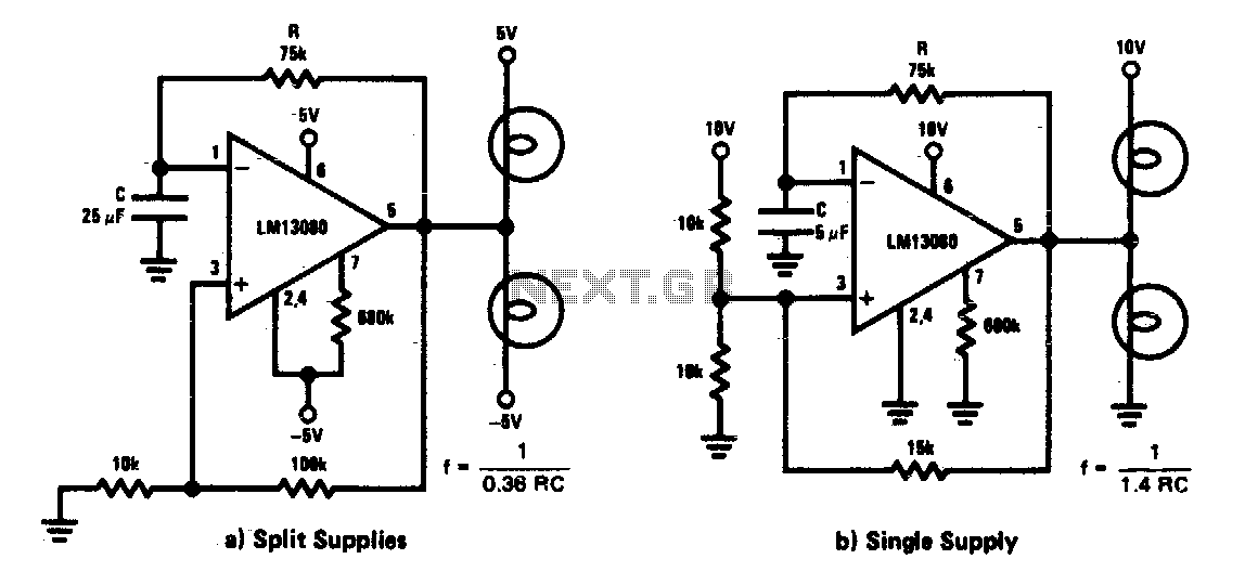
The low-frequency warning device circuit typically consists of an oscillator, which can be implemented using a 555 timer IC configured in astable mode. The frequency of oscillation can be adjusted by selecting appropriate resistor and capacitor values connected to the timer. The square wave output from the 555 timer is then used to control the operation of two incandescent lamps.
In the circuit, the output pin of the timer is connected to the base of a transistor, which acts as a switch to drive the lamps. When the square wave output goes high, the transistor is turned on, allowing current to flow through the first lamp, illuminating it. As the output transitions to low, the transistor turns off, and the first lamp goes out. Simultaneously, a second transistor can be used to control the second lamp, ensuring that it turns on when the first lamp is off, creating an alternating flashing effect.
To enhance the circuit's performance, diodes may be employed to prevent back EMF from the inductive load (if relays are used) from affecting the oscillator. Additionally, capacitors can be added for stability, and resistors can be employed for current limiting to protect the lamps and transistors from excessive current.
The design of this circuit is straightforward, making it suitable for applications such as warning signals in various environments, where visual alerts are necessary. The alternating flash of the lamps serves to attract attention effectively, making it an efficient warning device.This circuit is a low frequency warning device. The output of the oscillator is a square wave that is used to drive lamps or small relays The circuit alternately flashes two incandescent lamps. 🔗 External reference
Related Circuits
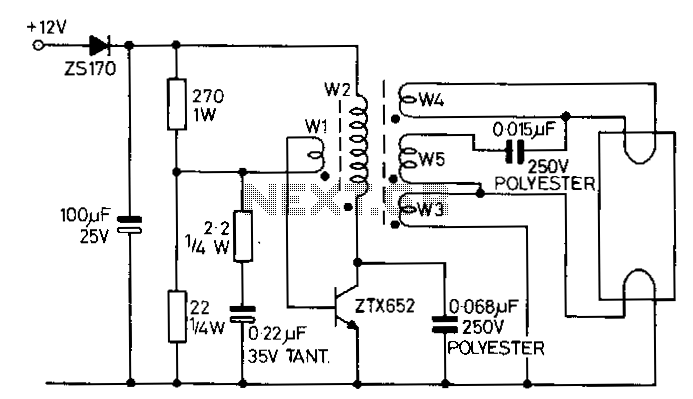
This circuit is designed to drive an 8-W fluorescent lamp from a 12-V power source using a cost-effective inverter based on the ZTX652 transistor. The inverter operates with supply voltages ranging from 10 to 16.5 V, making it suitable...
L293D Schematic diagram. The L293D division supplies power to the chip and its controlled motors, enabling the connection of motors with a higher voltage power supply than the chip itself. The separation of power circuits and electric motors may...
Savings on electricity bills can be achieved by utilizing alternative power sources. The photovoltaic module, or solar panel, described here can provide a power output of 5 watts. Under full sunlight conditions, the solar panel generates an output voltage...
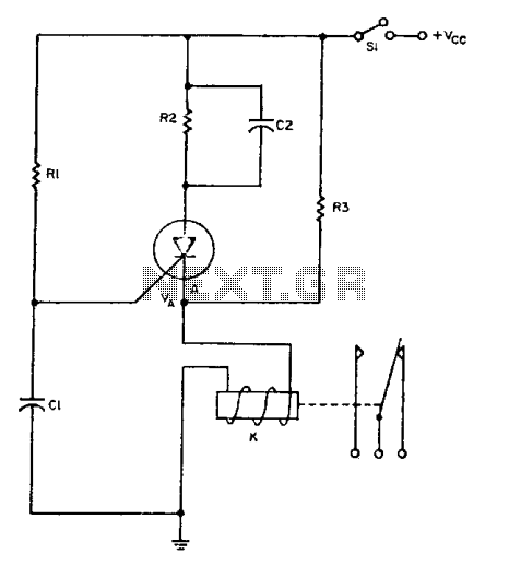
The relay operates for a specific duration, td, after power is applied, followed by an operating time, tc. The SCR activates when the voltage across capacitor Ci reaches a threshold voltage, VA. This action energizes the relay, which remains...
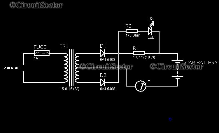
In today's world, owning a car battery charger at home has become essential. Having one readily available can help prevent starting issues caused by battery problems. While purchasing a commercial battery charger can be expensive, the components required for...

The 2N4391 features a low ON resistance of 30 ohms and a high OFF impedance of less than 0 pF when in the off state. With appropriate layout and an optimal switch configuration, the stated performance can be easily...