
LM3914 Low Power LED Voltmeter

This low-power voltmeter circuit is designed to effectively monitor battery voltage levels in alternative energy systems, ensuring that users can maintain optimal battery performance. The expanded scale voltmeter is particularly beneficial for applications requiring precise voltage readings, as it allows for small voltage increments to be displayed clearly. The low power consumption of the circuit is a critical feature, especially for systems relying on limited energy sources such as solar panels.
The blinking mode of the LED indicators not only conserves battery life but also provides a user-friendly interface that minimizes distractions. In the high-power mode, the continuous illumination of the LED can be advantageous for quick checks in environments where immediate visibility is required. The choice of LED colors enhances both functionality and aesthetic appeal, allowing users to customize the display according to their preferences.
When selecting components, the use of the CMOS ICM7555 timer is recommended for applications where energy efficiency is paramount, particularly in systems with small batteries. This choice can significantly extend the operational life of the battery, making it an ideal solution for portable applications.
Furthermore, the compatibility with common charge controllers and low voltage disconnect circuits underscores the versatility of this voltmeter circuit. By integrating such systems, users can ensure that their batteries are not only monitored but also protected from over-discharge, thereby enhancing the longevity and reliability of their energy systems. Overall, this voltmeter circuit is a valuable addition to any alternative energy setup, providing essential monitoring capabilities while maintaining low power consumption.This is a low power voltmeter circuit that can be used with alternative energy systems that run on 12 and 24 volt batteries. The voltmeter is an expanded scale type that indicates small voltage steps over the 10 to 16 volt range for 12 volt batteries and over the 22 to 32 volt range for 24 volt batteries.
Power consumption can be as low as 14mw wh en operated from 12V and 160mw when operated from 24V. It is possible to set the meter to read equal steps across a variety of upper and lower voltages. The meter saves power by operating in a low duty-cycle blinking mode where the LED indicators are only on and consuming power briefly during a repeating 2 second cycle. The circuit may be switched to a high power mode where the active LED stays on at all times. Different colored LEDs may be used for the voltage level indicators, this allows the battery state to be read in the dark.
With the new blue LEDs, it is possible to have a nice looking rainbow of colors using two each of red, amber, yellow, green, and blue LEDs. The circuit will also work with inexpensive and common red LEDs. If the circuit is to be used in sunlight, ultra-bright LEDs should be used, although even those may be hard to read without some kind of sun shield.
Typical uses include the monitoring of portable battery operated systems and indoor wall mounted home power system charge indicators. The cost of the parts for the circuit is around $25. 00 (US) and the parts are commonly available, except for the optional blue LEDs. If blue LEDS are used, expect to pay a premium for them, they cost several dollars each, compared to around 15 cents for the other colors.
The blue LEDs do look nice in any case. The circuit may be built with either the CMOS ICM7555 timer or the more common bipolar 555 timer. The 7555 timer will provide much more efficient operation and should be used for systems with small batteries. The volt meter works nicely with the solar charge controller and low voltage disconnect circuits described in the home-brew section of Home Power #60 and #63.
🔗 External reference
Related Circuits
This circuit operates at 73 MHz and is designed for controlling halogen lights through radio frequency remote control. The primary function is to toggle the power state of a halogen lamp. When the button on the remote control is...
The clock circuit above uses seven ICs and 19 LEDs to indicate binary coded decimal time. The LEDs can be arranged so that each horizontal group of 3 or 4 LEDs represents a decimal digit between 0 and 9...
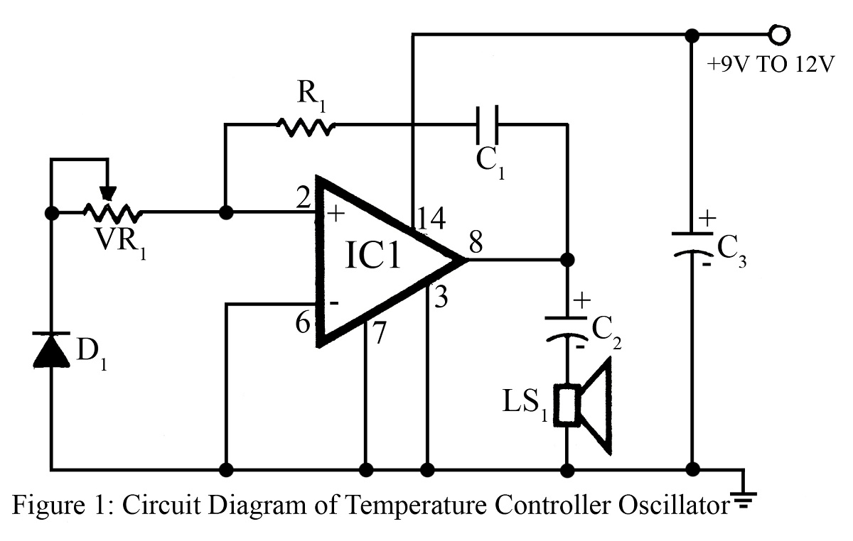
The output frequency or tone of this oscillator circuit varies with the temperature at which the input germanium diode is maintained. The reverse resistance of D1 ranges from 500 ohms to 10 k ohms when the temperature fluctuates between...
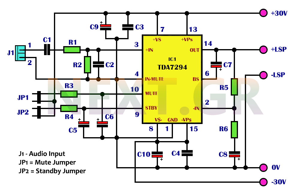
The integrated TDA7294 from SGS Thomson is a high-frequency acoustic power amplifier that boasts true high-precision specifications, making it suitable for various applications. Its standout feature is the significantly higher output power compared to typical amplifiers with similar distortion...
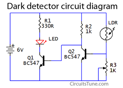
This is a basic dark detector or sensor circuit diagram based on a photoresistor (LDR) and a few components. The dark detector circuit utilizes a photoresistor (LDR) as the primary sensing element. The LDR is a light-dependent resistor that changes...
This project involves a 12V LED lamp circuit that is notably simple. The circuit comprises five resistors and fifteen super bright white 5mm LEDs, which are readily available at low prices. It is compatible with any type of 12-volt...