
LM78S40 5V to 15V Step-up Voltage Regulator

The described circuit employs a DC-DC boost converter topology to achieve the step-up conversion from 5V to 15V. The fundamental principle behind this operation is the ability to store energy temporarily in an inductor and then release it at a higher voltage.
The circuit typically consists of the following components: an inductor, a switch (usually a transistor), a diode, and a capacitor. The inductor is connected to the input voltage source (5V in this case) and the switch is periodically opened and closed to control the energy transfer. When the switch is closed, current flows through the inductor, storing energy in the magnetic field. When the switch opens, the inductor attempts to maintain the current flow, and this results in a voltage spike that is higher than the input voltage.
The diode is placed in such a way that it allows the current to flow to the output capacitor when the switch is open, preventing the current from returning to the input. The capacitor smooths the output voltage to provide a stable 15V output. The output voltage can be adjusted by modifying the duty cycle of the switching signal, which controls the time the switch remains closed relative to the time it is open.
In practice, the efficiency of this boost converter circuit is influenced by several factors, including the choice of components, switching frequency, and load conditions. While the circuit can achieve the desired voltage increase, it is essential to recognize that the output power cannot exceed the input power, hence the absence of power gain. Proper thermal management and component selection are crucial to ensure reliable operation and to prevent overheating during extended use.We can do a step-up conversion without using transformer. Using this circuit, a 5V DC source can be converted into 15V. Please note that there is no power gain.. 🔗 External reference
Related Circuits
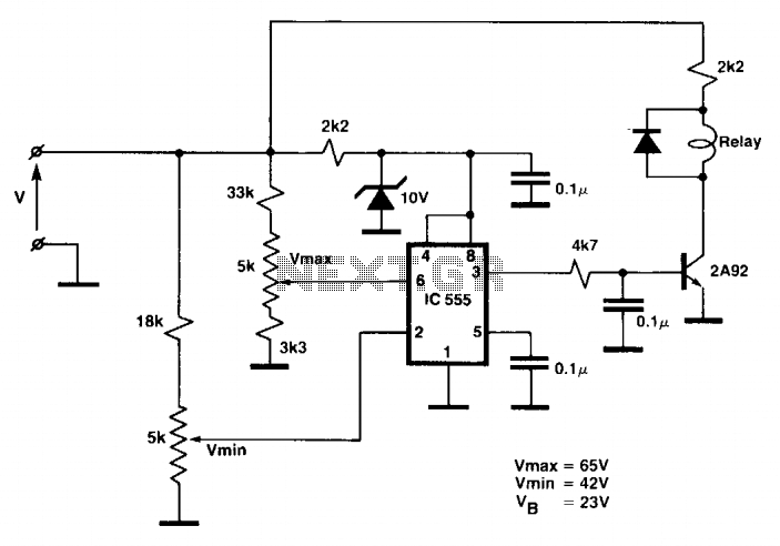
While the battery is charging, its voltage is measured at V. If the measured voltage is lower than the minimum threshold, the relay will be activated, connecting the charger circuit. When the battery voltage exceeds the maximum set point,...
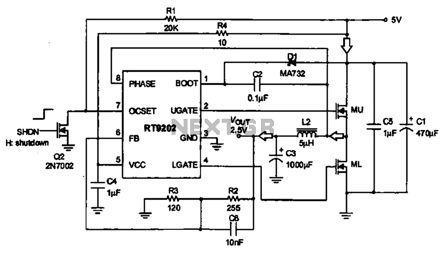
A 5V to 2.5V voltage regulator circuit is designed for use in computer motherboards. At its core, this circuit utilizes the RT9202 power management chip. The RT9202 functions as a switching pulse generating circuit, which, upon startup, converts a...
This circuit demonstrates that microprocessors, PCs, and modern ultra-accurate Digital-to-Analog Converters (DACs) are excessive for controlling four relays in sequence based on a control voltage ranging from 2.4 V to 12 V. By utilizing equal resistors in a ladder...
A voltage-to-frequency converter (VFC) circuit is illustrated in the schematic diagram below. The circuit utilizes a 555 integrated circuit (IC) as the central component of its operation. The voltage-to-frequency converter (VFC) is a crucial electronic circuit that converts an input...
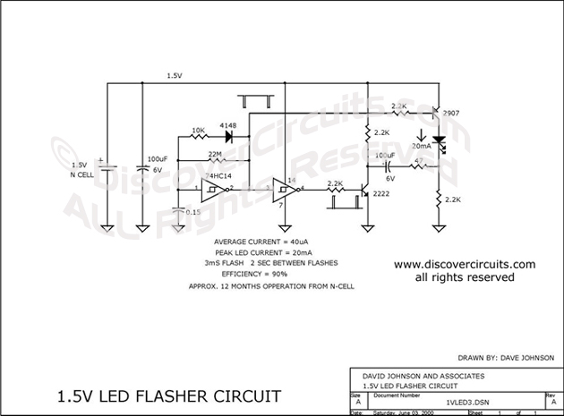
This circuit is designed to extract additional energy from an alkaline battery cell by incorporating two transistors into a configuration similar to a previously mentioned design, thereby enhancing efficiency. A standard 1.5-volt alkaline N cell is capable of powering...
This is a power supply circuit that produces a voltage range of 12 to 24 V. It is straightforward, requiring only a bridge rectifier, a filter capacitor, and a transformer, without the need for a regulator. A bridge rectifier...