
Voltage Levels Control Relays
This circuit effectively utilizes a resistor ladder network to create a series of defined voltage levels that correspond to the sequential activation of relays. The use of equal-value resistors ensures that the voltage drop across each resistor is uniform, facilitating predictable relay activation at specified control voltages. The choice of a stabilized power supply is crucial to maintain consistent relay operation, particularly as variations in supply voltage could lead to unintended relay behavior.
The circuit employs a BC548 transistor to drive the first relay, which is suitable for applications where the relay's coil resistance is maintained above the specified threshold. The design considerations for the operational amplifier (op-amp) are critical; the 741 op-amp's limitations necessitate careful selection of input voltage ranges to ensure reliable operation. For applications requiring lower voltage switching, the LM324 offers a versatile alternative, while the TS924 provides enhanced performance for higher voltage applications, albeit with its own constraints.
Overall, this circuit is an efficient solution for controlling multiple relays with minimal complexity, eliminating the need for more advanced microprocessor-based systems in scenarios where such sophistication is unwarranted. The design's simplicity, combined with the use of readily available components, makes it an attractive option for various electronic control applications.This circuit proves that microcoprocessors, PCs and the latest ultra-accurate DACs are overkill when it comes to controlling four relays in sequence in response to arising control voltage in the range 2. 4 V 12 V. By using equal resistors in ladder network R1-R5, equal intervals are created between the voltages that switch on the relays in seque
nce. Each resistors drops 1/5th of the supply voltage or 2. 4 V in this case, so we get +2. 4 V = Re1, +4. 8 V = Re2, +7. 2 V = Re3, +9. 6 V = Re4. Obviously, these switching levels vary along with the supply voltage, hence the need to employ a stabilised power supply. Looking at the lowest level switching stage, when the control voltage exceeds 2. 4 V, IC1 will flip its output to (nearly) the supply level. The resulting current sent into the base of T1 is limited to about 1 mA by R6. With T1 driven hard, relay Re1 is energised by the collector current. Because the BC548 has a maximum collector current spec of 100 mA, the relay coil resistance must not be smaller than 120 ohms.
Nearly all current consumed by the circuit goes on account of the relay coils, so depending on your relays a pretty hefty power supply of up to 500 mA may be required. When dimensioning the ladder network to create the desired switching levels, it is good to remember that the 741 will not operate very well with input voltages below 1.
5 V or above 10. 5 V, while voltage levels outside the supply range (i. e. , negative or above +12 V) are out of the question. If you do need a switching level in the range 0-1. 5 V, consider using an LM324, which contains four opamps in one package. For the high side of the range (10. 5 to 12 V), a TL084 or a rail-to-rail` opamp like the TS924 is required. However, the TS924 cannot be used with supply voltages above 12 V. Be the first of your friends to get free diy electronics projects, circuits diagrams, hacks, mods, gadgets & gizmo automatically each time we publish. Your email address & privacy are safe with us ! 🔗 External reference
Related Circuits
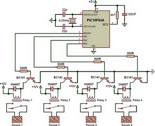
This is a relay driver based on a PIC16F84A microcontroller. The board includes four relays, allowing control of four distinct outputs. The relay driver circuit utilizing the PIC16F84A microcontroller is designed for controlling multiple devices or systems through relay activation....
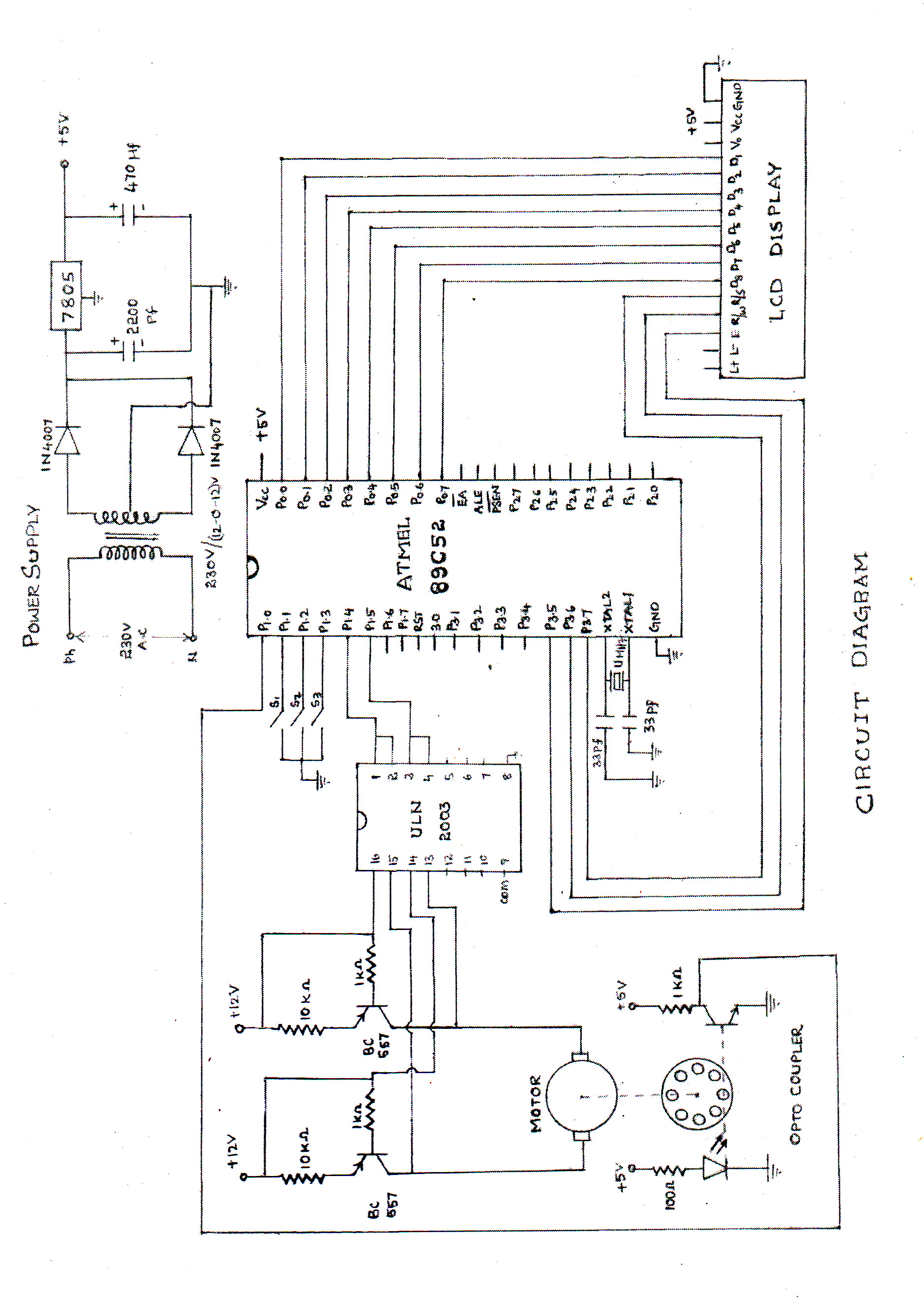
The speed of the DC motor is controlled using an ATMEL89C52 microcontroller, with feedback provided by an optocoupler. The circuit diagram can be viewed above (click on the diagram for a larger view). The motor speed is regulated by...

This article reviews basic servo systems and the development of fault-tolerant feedback systems for servo applications. It discusses controller receiver circuit design, appropriate PC-board receiver circuit layout, and the encoder's signal cable and termination. Various types of industrial feedback...
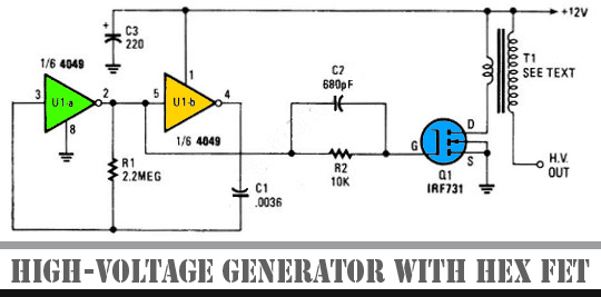
The schematic diagram below illustrates a high voltage generator circuit. This circuit employs a 4049 hex inverter configured as an oscillator, and it can utilize an ignition transformer from an automotive engine. A fly-back transformer may also be suitable....
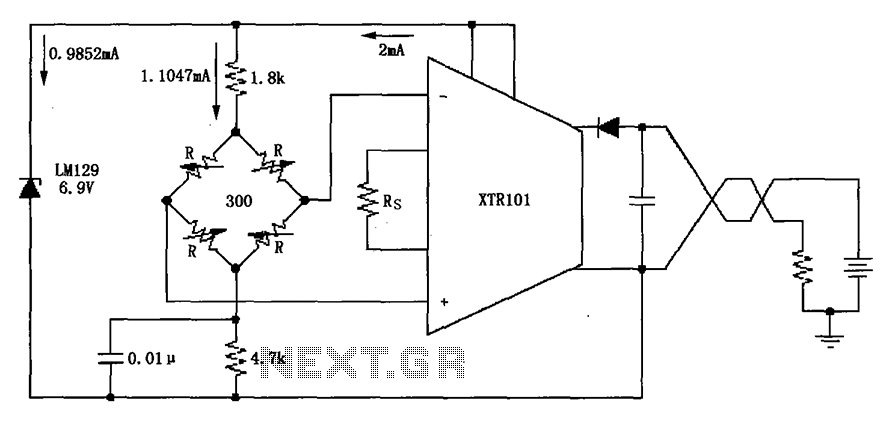
The circuit utilizes the LM129 voltage regulator to produce a 6.9V voltage reference, supplying a current of 1.0147mA from the 6.9V reference voltage to the bridge. The bridge may consist of varistor-type pressure sensors. The LM129 voltage regulator is a...
This circuit can provide various utilities, such as an alarm, door opening mechanism, or lighting control for a garden or courtyard, depending on the user's creativity. The operating principle relies on the characteristics of a photoelectric photocell, which alters...