
9 Volt 2 Amp Power Supply
The described circuit is a linear voltage regulator circuit utilizing the 78S09 voltage regulator, which is specifically designed to convert a higher DC input voltage into a stable 9V output. The 78S09 is capable of supplying a maximum continuous output current of 2 amps, making it suitable for various applications requiring a reliable power source.
At the input of the circuit, a 1N5400 diode is employed to provide reverse polarity protection. This diode is rated for a maximum current of 3 amps and can withstand voltages up to 40 volts, ensuring that the circuit is safeguarded against accidental reverse connections. The use of this diode is critical in preventing damage to the voltage regulator and downstream components.
Capacitor C1 is included at the input to enhance the smoothing of the input voltage. This capacitor helps to filter out any ripples or noise present in the input supply, ensuring that the voltage regulator receives a clean DC voltage. The value of C1 is typically chosen based on the input voltage and the load conditions but is often in the range of several microfarads to tens of microfarads.
The output stage of the circuit includes capacitor C2, which serves as an additional filter to further stabilize the output voltage. This capacitor helps to reduce output noise and improves the transient response of the regulator. For applications involving logic circuits, it is advisable to add a 100nF capacitor in parallel with C2. This capacitor is effective in filtering high-frequency switching noise that may be generated by digital components, ensuring that the logic circuits operate reliably without interference.
Overall, this circuit configuration is straightforward yet effective, providing a well-regulated output voltage suitable for various electronic applications. The inclusion of reverse polarity protection and additional filtering capacitors enhances the robustness and performance of the power supply circuit.There is little to be said about this circuit. All the work is done by the regulator. The 78S09 can deliver up to 2 amps continuous output whilst maintaining a low noise and very well regulated supply. The circuit will work without the extra components, but for reverse polarity protection a 1N5400 diode is provided at the input, extra smoothing being provided by C1.
The output stage includes C2 for extra filtering, if powering a logic circuit than a 100nF capacitor is also desirable to remove any high frequency switching noise. 🔗 External reference
Related Circuits
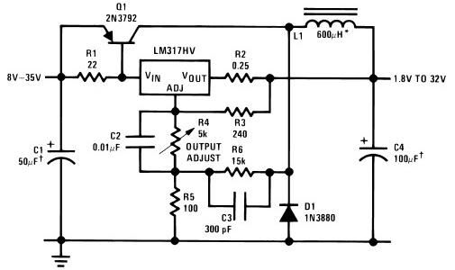
The circuit diagram of this LM317 power supply electronic project requires a few external components. The input voltage for this project must be between 8 and 35 volts, providing a variable output voltage ranging from 1.8 volts to 32...
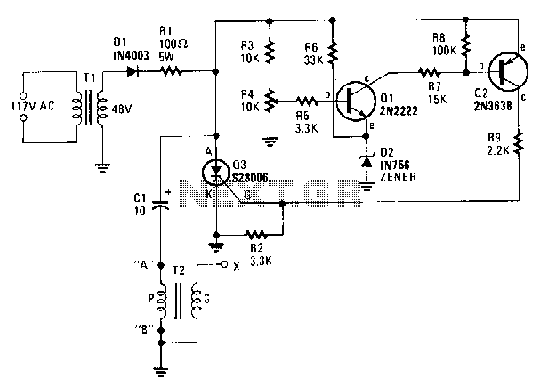
A step-down transformer T1 reduces the incoming line voltage to approximately 48 Vac, which is then rectified by diode D1. The resulting direct current charges capacitor C1 through a current-limiting resistor R1 to a voltage level set by R4....
There is no substitute for sheer power—low-efficiency speakers, outdoor sound systems, or perhaps the full dynamic range of a high-power amplifier. Whatever the requirement, this super power module should meet the needs. The amplifier can be divided into three...
Diode detectors are good at changing AC into DC, even at high frequencies. The main problem with diode detectors have inherent nonlinearities, particularly for small signals. To minimize the effects of the nonlinearities, a preamplifier boosts the amplitude of...
This diagram originates from the Progressive Communications Receiver featured in most recent ARRL Handbooks. The amplifier is utilized wherever an intermediate frequency (IF) amplifier is necessary. W6BKY has published an article on Hamradio-online that details the construction of this...
The circuit was submitted by an individual from Newtownabbey, Northern Ireland. It has an exceptionally fast high frequency response, as demonstrated by applying a 100kHz squarewave to the input. All graphs were produced using Tina Pro. The circuit in question...