
Logarithmic resistor ladder
The logarithmic resistor ladder circuit operates by utilizing a carefully structured arrangement of resistors and switches, allowing for precise control over the attenuation of an input signal. Each resistor in the ladder is selected to provide a specific resistance value that contributes to the overall logarithmic response of the circuit. The switches, controlled by a binary code, determine which resistors are included in the signal path, thereby adjusting the attenuation based on the selected digital input. This configuration enables the circuit to produce a wide range of output levels while maintaining fidelity to the logarithmic perception of sound, which is crucial in audio applications.
In designing the circuit, attention must be paid to the choice of resistors and the configuration of the stages. The use of constant input or output resistance helps to isolate the stages from one another, ensuring that the performance of one stage does not adversely affect the others. This is particularly important in applications where precision and consistency are required across the entire range of operation. The reordering of stages can be strategically employed to optimize the input resistance characteristics, which can further enhance the performance of the overall circuit.
The implementation of this circuit in audio devices is significant, as it allows for a more natural representation of audio levels, aligning with the logarithmic nature of human hearing. By providing a logarithmic response, the circuit can effectively handle a wide dynamic range, making it suitable for various audio processing tasks. The development of logarithmic digital-to-analog converters has expanded the possibilities for high-performance audio applications, allowing for greater flexibility and precision in sound reproduction.A logarithmic resistor ladder is an electronic circuit composed of a series of resistors and switches, designed to create an attenuation from an input to an output signal, where the logarithm of the attenuation ratio is proportional to a digital code word that represents the state of the switches. The logarithmic behavior of the circuit is its ma in differentiator in comparison with digital-to-analog converters in general, and traditional R-2R Ladder networks specifically. Logarithmic attenuation is desired in situations where a large dynamic range needs to be handled. The circuit described in this article is applied in audio devices, since human perception of sound level is properly expressed on a logarithmic scale.
As in digital-to-analog converters, a binary word is applied to the ladder network, whose N bits are treated to represent an integer value according the relation: This example circuit is composed of 4 stages, numbered 1 to 4, and an additional leading Rsource and trailing Rload. Each stage i, has a designed input-to-output voltage attenuation ratioi as: The different stages 1. N should function independently of each other, as to obtain 2N different states with a composable behavior.
To achieve an attenuation of each stage that is independent of its surrounding stages, either one of two design choices is to be implemented: constant input resistance or constant output resistance. The circuit as depicted above, can also be applied in reverse direction. That correspondingly reverses the role of constant-input and constant-output resistance equations. Since the stages do not influence each other`s attenuation, the stage order can be chosen arbitrarily.
Such reordering can have a significant effect on the input resistance of the constant output resistance attenuator and vice versa. Multiplying DA-converters with logarithmic behavior were not known for a long time after that. An initial approach was to map the logarithmic code to a much longer code word, which could be applied to the classical (linear) R-2R based DA-converter.
Lengthening the codeword is needed in that approach to achieve sufficient dynamic range. This approach was implemented in a device from Analog Devices inc. , [3] protected through a 1981 patent filing. [4] 🔗 External reference
Related Circuits
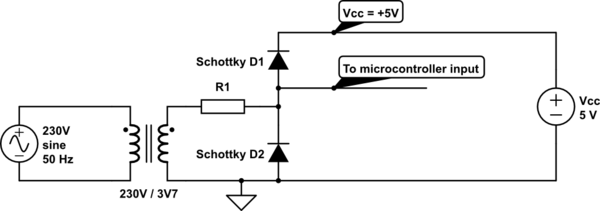
Provide zero crossing detection for the controller. Using the schematic below, a square wave signal was generated, representing the positive and negative half-periods. The issue is that the resistor needs to be quite large, which can lead to excessive...
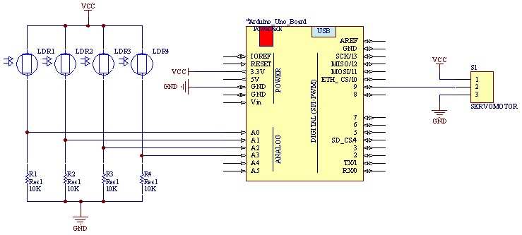
The movement of the servo is determined by the output values of the photoresistors. The impedance of these sensors changes with the amount of light incident upon them. The servo's position shifts towards the sensor that detects less light....
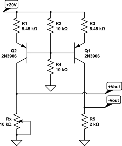
A functional circuit utilizing an operational amplifier (op-amp); however, the instructor indicated that op-amps can be challenging to work with and provided transistors as an alternative. Operational amplifiers (op-amps) are versatile components commonly used in various electronic circuits for...
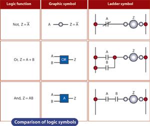
The ladder logic programming method is a widely utilized approach in the programming of electrical simulation schematic control systems. This method primarily serves to make decisions regarding whether specific load circuits should be opened or closed. To comprehend ladder...
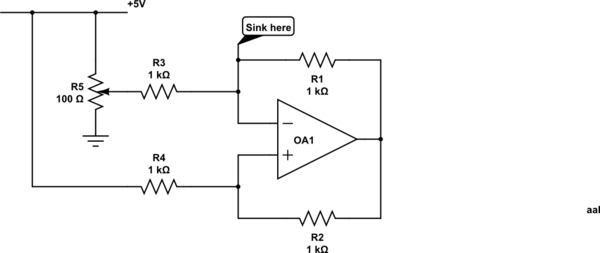
Control a current through several current-mirror devices (specifically the IREF pin on the TLC5940) using a single potentiometer. A modified Howland current source has been utilized, which works adequately with the specified resistor values for dimming an LED. However,...
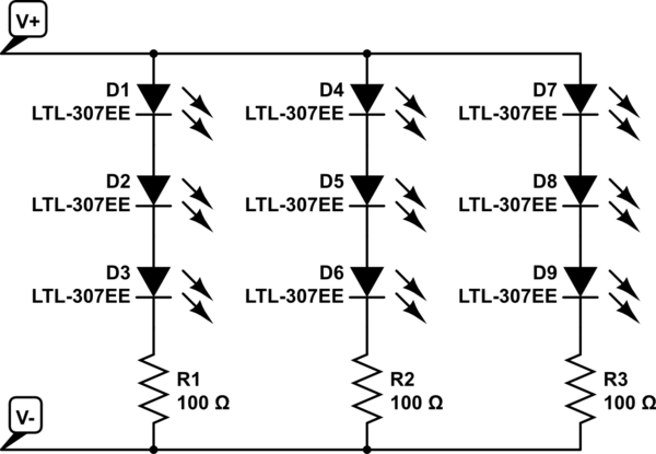
The project involves installing LED strips in a car's tail lamps to replace conventional bulbs. The required lengths for the LED strips are 16 inches, 15 inches, and 14 inches to fit properly within the housings. The selected LED...