
photoresistors servo and arduino

The described circuit utilizes an Arduino microcontroller to manage the operation of a servo motor based on input from multiple photoresistor sensors. The photoresistors are arranged in a cross pattern around the servo, allowing for directional sensing of light intensity. Each photoresistor is connected to an analog input pin on the Arduino, enabling the microcontroller to read the varying voltage levels corresponding to the light intensity detected by each sensor.
The servo motor is controlled through a PWM signal generated by the Arduino. It is essential to calibrate the servo's position accurately, ensuring that the 0-degree position corresponds to the Up orientation, the 90-degree position to the Right, and the 180-degree position to the Down. The code implemented in the Arduino continuously monitors the values from the photoresistors in real-time, comparing the readings to determine which sensor is receiving the least amount of light.
When the code identifies that a specific sensor (top, right, left, or bottom) has the lowest light reading, it commands the servo to move to the corresponding position. For example, if the upper photoresistor detects less light than the others, the servo will rotate to the Up position. This functionality allows the system to respond dynamically to changes in light conditions, making it suitable for applications such as solar tracking systems.
In terms of hardware, the servo motor can be replaced with a more robust model if needed, especially in applications requiring the movement of heavier loads. The inclusion of a 12V relay in the circuit would facilitate the control of a larger servo motor, expanding the potential applications of this design. This setup could be particularly advantageous for solar panels, ensuring they are always oriented towards the sun for optimal energy capture.
The schematic diagram would typically illustrate the connections between the Arduino, photoresistors, servo motor, and relay, providing a clear visual representation of the circuit layout. Proper power management and component ratings should be considered to ensure the reliability and efficiency of the system.The movement of the servo depends on the output value of the photoresistors. The impedance of the sensors varies with the light that incident on them. The position of the servo always changes toward the sensor with less light. There are four light sensors. One Up, one right, one down and another on the left. The servo can only move 180 degrees. Ive divided this range in three part. The positions are Up, Right and Down. 0 degrees is the position Up, 90 degrees is the position on the right and finally, 180 degrees is the inferior position Down. Therefore, the code programmed here moves the servo Up if the upper sensor or the left sensor have less light than the others.
It goes to the right if the Right sensor has less light and it changes his position to the inferior position if the Down sensor has less light than the other. On the picture below you can appreciate the light sensors on the sides of the box and the servo in the center with his stick looking down.
The USB cable goes out from the inferior side of the box. In the Figure 1 and 2 you can see how I`ve held the servo on the box, how the wires have been placed and the position of the photoresistors. The components are assembled on Arduino as in the schematic below. The best way to see the results is to watch it in a video. In this video you are going to watch how the stick of the servo responds when I cover the light from a photoresistor.
I was thinking in using a big servo controlled by a 12V relay with the purpose of moving heavy stuff. For instance, a solar panel that always moves toward the greatest source of light. 🔗 External reference
Related Circuits
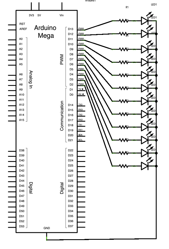
Connect the longer, positive legs (anodes) of 12 LEDs to digital pins 2-13 through 220-ohm current limiting resistors. Connect the shorter, negative legs (cathodes) to ground. The circuit will sequentially illuminate each LED from the lowest pin to the...
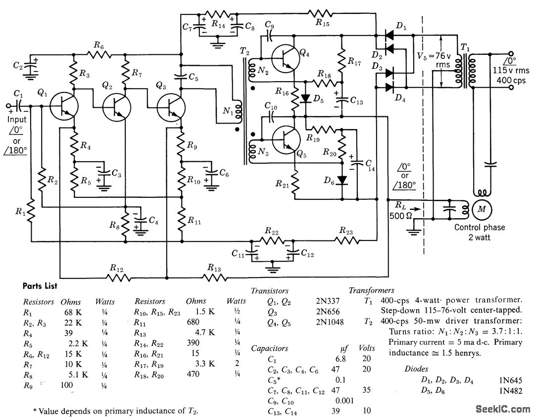
The circuit comprises a direct-coupled preamplifier and driver stages, featuring significant direct current (d-c) feedback to stabilize bias conditions. The voltage gain of the amplifier, when the feedback loop is closed, is 10,000. The overall efficiency of the circuit...
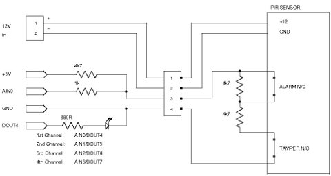
Security system sensors such as motion detectors, reed switches, pressure mats, glass-break detectors, infrared beams, and conductive film can be very useful for various applications, including home automation systems, interactive art installations, and security systems. Almost all security system...
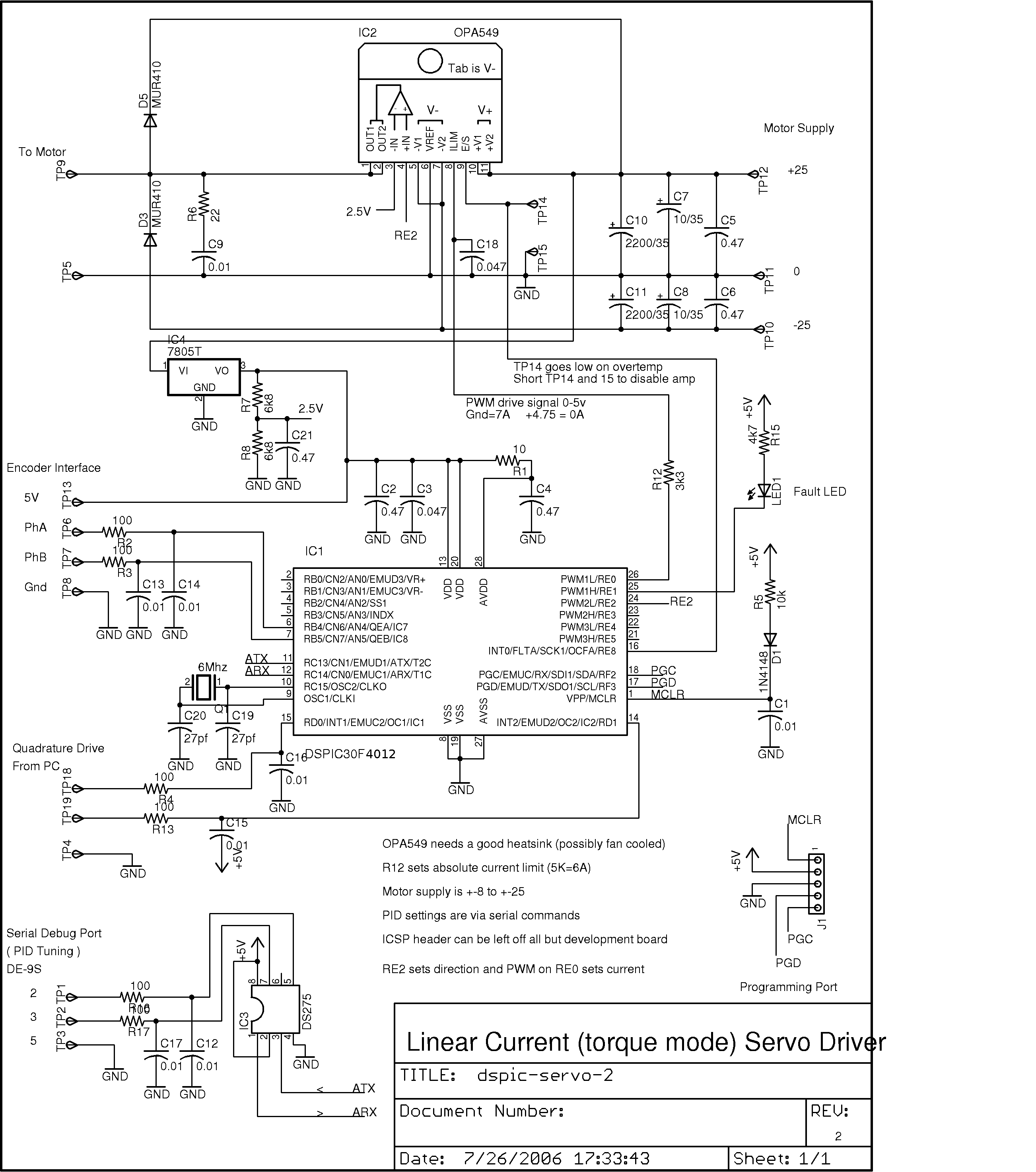
This project was developed as a cost-effective solution for driving small DC brushed motors as positioning servos for a desktop-sized CNC machine. The board interfaces with the PC through two pins of a parallel port, utilizing a quadrature drive...

This circuit is a MOSFET power amplifier configured in an OCL (Output Capacitor-Less) topology. It delivers an output power of 100 watts and can utilize MOSFETs such as K134 and J49 or J162 and K1058. When driving an 8-ohm...
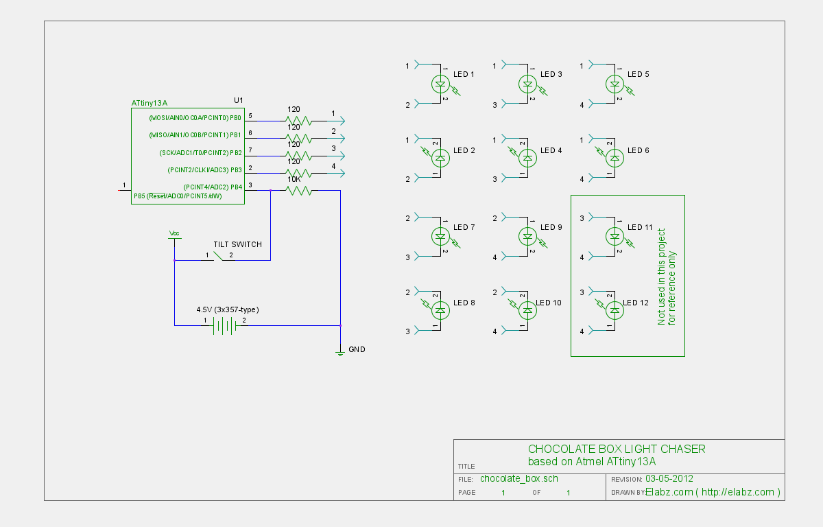
Transform a standard chocolate box into an impressive LED blinking display using an ATTiny13 AVR microcontroller, Arduino IDE, and several electronic components. The project involves creating an eye-catching LED display housed within a chocolate box. The core of the circuit...