
LOGIC DESIGNER
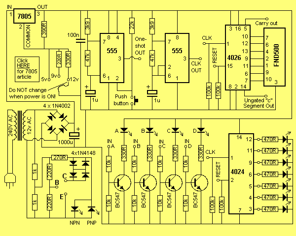
The logic designer serves as a versatile platform for testing and evaluating digital circuits. It comprises various building blocks that can be interconnected to form different configurations, enabling users to create a range of counting and testing stages. The modular nature of the design allows for extensive customization, making it suitable for educational purposes, prototyping, and experimentation.
The primary focus of the logic designer is to facilitate the testing of digital circuits, which includes components such as logic gates, flip-flops, counters, and multiplexers. Each of these components can be represented on the board, allowing for a hands-on approach to learning and understanding digital logic principles. The interconnectivity of these blocks means that users can explore various logical operations and configurations, leading to a deeper comprehension of digital circuit behavior.
Key features of the logic designer include a user-friendly interface that allows for easy manipulation of the building blocks, clear labeling for each component, and the ability to visualize connections in real-time. This setup not only aids in the testing process but also provides immediate feedback on circuit functionality. Additionally, the board is designed to accommodate various power supply options, ensuring compatibility with different digital components.
It is important to note that the logic designer is exclusively intended for digital circuits. As such, it will not provide meaningful results when used with analog devices, such as audio amplifiers or radio frequency circuits. Users should focus on digital logic applications to fully leverage the capabilities of the logic designer. This specialized design ensures that the unit remains a focused and effective tool for testing and learning within the realm of digital electronics.The logic designer is filled with features. It would not be possible to list all the possible combinations of the unit as the various building blocks on the board can be interconnected to obtain a wide variety of counting and testing stages. You will be able to see what we mean after you build the project and start to interconnect the blocks yourself.
But we can give an outline of some of the features we have specially incorporated into the board. You can consider the DESIGNER as a piece of test equipment. It is specially designed for testing digital circuits. In fact it will only test digital circuits. So don`t expect to get any results from an audio amplifier or radio. The type of digital ci 🔗 External reference
Related Circuits
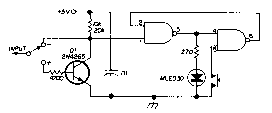
By connecting this circuit to a powered logic device, an indication of its status can be obtained. If the circuit is open, neither of the test lamps will illuminate. If the circuit is grounded, the low (or zero) lamp...
All of my turbine starts before the research on the ECU involved a very successful spark ignition. I thought (only briefly) of trying to add spark ignition to the ECU, but the mixture of delicate logic circuitry and perhaps...
Digital electronics tutorial about the Logic NOT Gate, also known as an Inverter, and the Logic NOT Gate Truth Table used in TTL and CMOS Logic Gate circuits. The Logic NOT Gate, or Inverter, is a fundamental building block in...
There are two switches: a memory disable switch and a pulse polarity switch. The memory disable switch is a push-button that resets the memory to a low state when pressed. The pulse polarity switch is a toggle switch that...
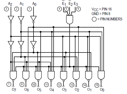
The Motorola SN54/74LS138 is recognized as a 1-of-8 decoder or demultiplexer, specifically engineered for high-speed bar memory chip select address decoding. The accompanying diagram illustrates the logic configuration of the SN54/74LS138 demultiplexer. According to the SN54 datasheet, the multiple...
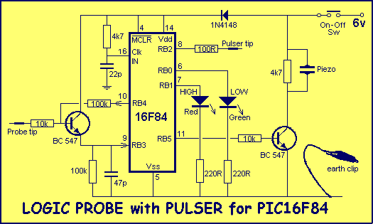
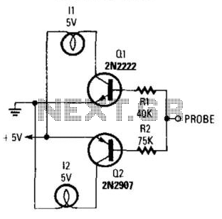
This project is a combination Logic Probe and Logic Pulser. It is capable of testing all sorts of digital and microcomputer projects. You will find it extremely handy when designing a project as the golden rule is to test...
Warning: include(partials/cookie-banner.php): Failed to open stream: Permission denied in /var/www/html/nextgr/view-circuit.php on line 713
Warning: include(): Failed opening 'partials/cookie-banner.php' for inclusion (include_path='.:/usr/share/php') in /var/www/html/nextgr/view-circuit.php on line 713