
Logic NOT Gate Tutorial with Logic Gate Truth Table
The Logic NOT Gate, or Inverter, is a fundamental building block in digital electronics, responsible for inverting the input signal. When a high logic level (1) is applied to the input, the output will be low (0), and vice versa. This behavior can be summarized in the Truth Table for the NOT Gate, which illustrates that the output of the gate is always the opposite of the input.
In TTL (Transistor-Transistor Logic) circuits, a NOT Gate typically consists of bipolar junction transistors (BJTs) configured to achieve the desired logic inversion. The characteristics of TTL NOT Gates include fast switching times and moderate power consumption, making them suitable for a wide range of applications in digital systems.
In CMOS (Complementary Metal-Oxide-Semiconductor) technology, the NOT Gate is implemented using complementary pairs of p-channel and n-channel MOSFETs. The CMOS NOT Gate offers advantages such as lower power consumption and higher noise margins compared to TTL. The output state is determined by the combination of the input signal applied to the gate terminals of the MOSFETs, ensuring that the output is the logical complement of the input.
Both TTL and CMOS NOT Gates can be represented in schematic diagrams, where the input is denoted by a single line entering the gate symbol, and the output is indicated by a single line exiting the opposite side of the symbol. The symbol for the NOT Gate is a triangle pointing to the right with a small circle at the output, indicating the inversion of the signal.
Understanding the operation of the Logic NOT Gate is crucial for designing more complex digital circuits, as it serves as the basis for constructing other logic gates and implementing various digital functions.Digital Electronics Tutorial about the Logic NOT Gate also called an Inverter and the Logic NOT Gate Truth Table used in TTL and CMOS Logic Gate circuits.. 🔗 External reference
Related Circuits
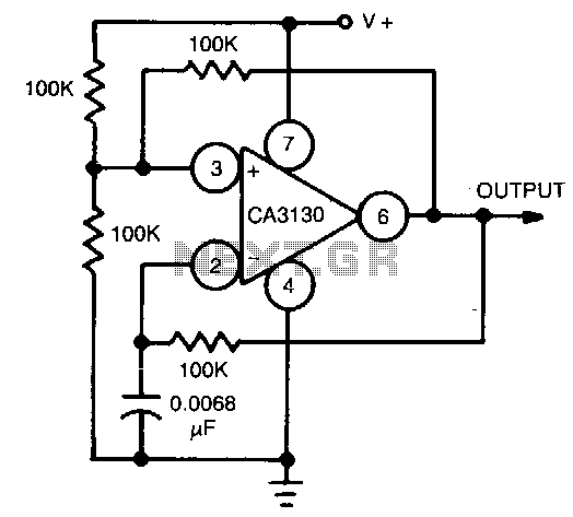
This circuit utilizes the CA3130 BiMOS operational amplifier, which operates at a frequency of 1 kHz. It features a rail-to-rail output swing, ensuring that the output can reach the supply voltage levels. The frequency of operation remains independent of...
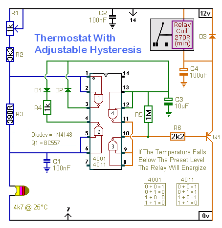
A thermostat doesn't try to maintain a constant temperature. In order to do so, it would have to keep switching on and off every few seconds. Instead, it keeps the temperature within a specific range. When the preset temperature...
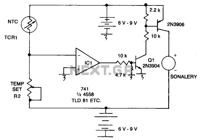
As the resistance (Rl) increases with a decrease in temperature, the output of integrated circuit IC1 becomes positive, activating transistor Q1. When Q1 conducts, it also triggers transistor Q2, which in turn activates the audible alarm. The threshold level...
This receiver is designed around the widely used ZN414 integrated circuit, which covers the medium wave band from approximately 550 to 1600 KHz. The coil and tuning capacitor can be salvaged from an old medium wave radio to expedite...
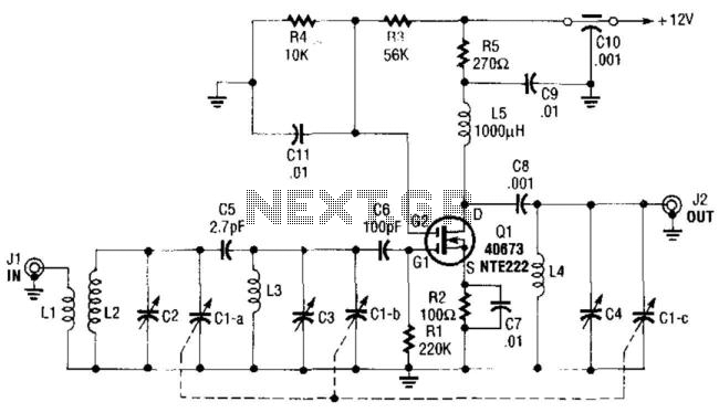
The use of a double-tuned input and a single-tuned output yields superior RF selectivity compared to equivalent single-tuned designs. Automatic Gain Control (AGC), if required, can be added to gate 2 of Q1 and should drive gate 2 negative...

The schematic below illustrates four methods of controlling a relay with a digital logic signal. Figure A can be used in most cases where the relay coil requires 100 mA or less and the input current is 2 milliamps...