
LOGIC PROBE with PULSER
The project integrates two essential tools for digital circuit diagnostics: a Logic Probe and a Logic Pulser. The Logic Probe is designed to detect the logic levels (high or low) in digital circuits, providing a visual indication through an LED or a sound signal. It can be used to troubleshoot and verify the functionality of various digital components, such as logic gates, flip-flops, and microcontrollers. The probe typically features a simple interface with a probe tip for contact with circuit nodes and a ground connection.
The Logic Pulser, on the other hand, is used to generate test signals, allowing the user to inject known logic levels into a circuit. This tool is particularly useful for testing the response of digital components to specific inputs, enabling designers to observe how circuits behave under different conditions. The pulser can be configured to produce square waves or single pulses, which can be adjusted for frequency and duration, depending on the testing requirements.
The combination of these two tools in a single device enhances the efficiency of the design and debugging process. The schematic for this project would typically include a microcontroller to manage the logic levels and signal generation, along with a series of resistors, capacitors, and transistors to form the necessary circuits for both the Logic Probe and Logic Pulser functionalities. Power supply considerations are also crucial, ensuring that the device operates within the specified voltage range for safe testing of various components.
In summary, this project serves as a versatile tool for engineers and hobbyists alike, facilitating the testing and verification of digital circuits by combining the functionalities of a Logic Probe and a Logic Pulser into one compact device.This project is a combination Logic Probe and Logic Pulser. It is capable of testing all sorts of digital and microcomputer projects. You will find it extremely handy when designing a project as the golden rule is to test everything in steps and stages during the design-and-construction process. If you are not sure how a Logic Probe or Pulser works, let me explain. 🔗 External reference
Related Circuits
A buffer amplifier is necessary for a typical pH probe to isolate its source resistance, which ranges from 10^6 to 10^9 ohms, from the external circuitry. Such an amplifier is illustrated in the... The buffer amplifier serves a critical role...
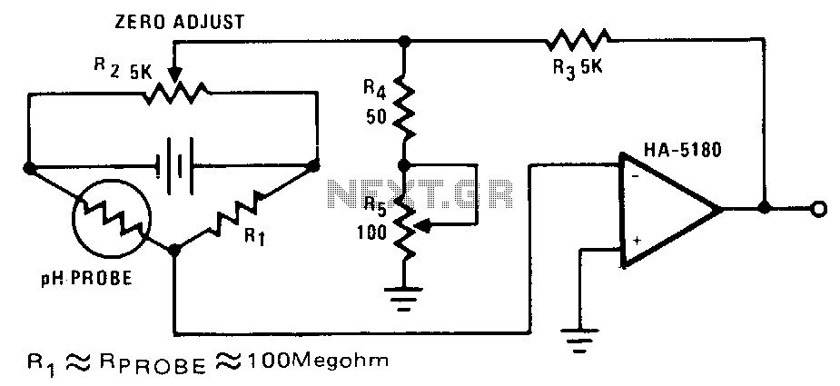
The highest sensitivity is attained when R1 is roughly equal to the probe resistance. The circuit can be calibrated to zero using R2, while R5 regulates the full-scale voltage. The relationship between pH and output voltage may not be...
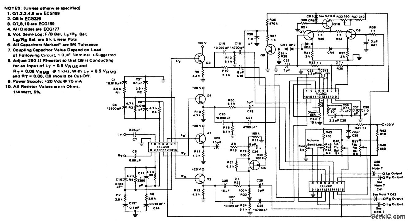
4-channel SQ logic decoder with a current drain of 75 mA at 20 volts. The input impedance is 2M ohms, and the output impedance is 2K ohms (courtesy of GTE Sylvania Incorporated). The 4-channel SQ logic decoder is an integrated...
This probe is useful for any low level RF work, and simply connects to your multimeter. The voltage shown will not be accurate, since this is a rectifier probe, but the measurements are good enough for you to be...
This tester is designed to locate stray electromagnetic (EM) fields. It can easily detect both audio and RF signals up to frequencies of around 100 kHz. However, this circuit is not a metal detector; it will detect metal wiring...
Using a modern multimeter to measure current can sometimes be difficult. Many of these meters will only measure up to one amp. However, many 112-volt DC powered projects draw a lot more than that. If you have ever thought...