
fADC Amplifier Circuit Simulations
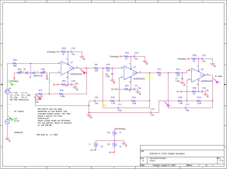
The described circuit employs a bandwidth-limited amplifier to enhance the signal integrity of a 40 MHz high-speed pipeline Analog to Digital Converter (ADC). The amplifier is crucial for shaping the waveform, ensuring that the signal is adequately processed for accurate digitization. The shaping time, which is critical for determining the response characteristics of the circuit, is derived from the time constant associated with the filter network. Specifically, the time constant, calculated as the product of resistance (205 Ω) and capacitance (110 pF), results in a value of 22.5 ns, which indicates the temporal response of the amplifier-filter arrangement.
The topology of the circuit features an amplifier followed by two cascaded two-pole active filters. This configuration is designed to optimize the frequency response and minimize noise, thereby enhancing the overall performance of the ADC. The filter's impulse response is particularly important; it is engineered to replicate the characteristics of a pulse generated by a photomultiplier tube, which is common in high-speed applications. The ability of the filter to produce a pulse that can be sampled at least twice on both the rising and falling edges is a key factor in ensuring compliance with the Nyquist-Shannon sampling theorem. This theorem asserts that to accurately reconstruct a signal, it must be sampled at a rate greater than twice its highest frequency component, which is achieved in this design.
Moreover, the gain of the amplifier is meticulously adjusted to ensure that a 5 mV single photoelectron (SPE) pulse—characterized as a triangular pulse with a width of 15 ns and a peak amplitude of 5 mV—results in a 12 mV output pulse at the ADC input. This translates to a six-count reading on the ADC, ensuring that the signal is sufficiently amplified for reliable digital representation. Overall, this circuit design exemplifies a well-structured approach to signal processing in high-speed applications, balancing amplification, filtering, and sampling to achieve optimal performance.A band-width limited amplifies shapes the waveform sampled by the 40 MHz high speed, pipeline Analog to Digital Converter (fast ADC, or fADC). It is well known that the shaping time is twice the time constant (peaking time), per pole of the filter network.
The time constant is (205 © x 110pF) = 22. 5ns. The amplifier-filter topology consists of an amplifier preceding two cascaded two-pole active filters. See the lower left corner of the front-end schematic. The response of the filter to an impulse (a pulse substantially like a photomultiplier pulse), yields a pulse that can be sampled at least twice on its rising, or falling edge by the fADC. This waveform easily satisfies the Nyquist Shannon sampling theorem. (Negligeable signal energy at half the sampling frequency) The gain is adjusted so that a 5 mV SPE (approximated by a triangular pulse 15ns wide at its base, 5mV high), produces a 12mV (six ADC count) pulse at the input of the fADC.
🔗 External reference
Related Circuits
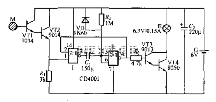
A two-battery powered light touch delay circuit designed for convenience at night. It can be placed on a bed pillow, and when the metal contact M under the capsule is touched, a small lamp will automatically light up. The...
The Clock Controller was designed as an exemplary application of the C programming language to manage timer0 interrupts, control a 7-segment LED display, and perform keypad scanning. It offers a 1-bit sink current output suitable for driving devices such...
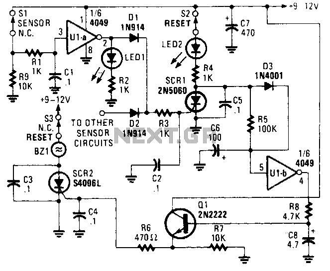
The alarm/sensor circuit is constructed using two SCRs, a transistor, a 4049 hex inverter, and several supporting components, which together create a closed-loop detection circuit featuring a delay mechanism. This delay allows entry into a protected area and deactivation...
This receiver is designed around the widely used ZN414 integrated circuit (IC) and operates within the AM band, covering frequencies from 550 to 1600 KHz. To utilize the receiver for Longwave frequencies, it is necessary to replace the coil...
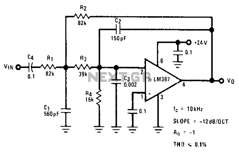
The circuit provides a passband gain of 1 with a corner frequency of 10 kHz, designed to eliminate high-frequency noise such as hiss, ticking, and popping sounds. This circuit operates as a low-pass filter, effectively attenuating frequencies above the specified...
The video master comprises a series of converters that allocate all video sources to unused UHF channels. These channels are then combined with standard TV channels, whether terrestrial or cable, into a single cable. This single cable can subsequently...
Warning: include(partials/cookie-banner.php): Failed to open stream: Permission denied in /var/www/html/nextgr/view-circuit.php on line 713
Warning: include(): Failed opening 'partials/cookie-banner.php' for inclusion (include_path='.:/usr/share/php') in /var/www/html/nextgr/view-circuit.php on line 713