
Logic level relay controller
4 74LSXX .0004 20 milliamps 8.2K 4 74XX .0008 40 milliamps 4.3K 4 74SXX .001 50 milliamps 3.3K 5 74HCXX .004 200 milliamps 1K 6 74HCXX .004 200 milliamps 1.3K 5 CD40XX .0003 15 milliamps 13K 12 CD40XX .0006 30 milliamps 18K Figure B can be used when the input voltage is the same as the relay coil voltage. The voltage on the emitter of the transistor will be about 0.7 volts less than the input, so a 12 volt relay would operate on 11.3 which should be close enough. No resistor is needed since the emitter follower configuration presents a high impedance at the input. The input current will be the relay coil current divided by the transistor gain. For example a 120 ohm relay coil will draw 100 mA at 12 volts and if the transistor gain is 50, the input current will be about 2 milliamps. Figure C can be used to provide additional gain when the input current is very small. You can also use a Darlington transistor in place of the two transistors which is a better approach, but this idea works just as well when you don't have a Darlington transistor handy. The overall gain will be the product of the individual gains of the two transistors or about 2500 for two transistor with a gain of 50 each. This will enable supplying over 250 mA to the relay with only 100 microamps of input current. The R value will depend on the input voltage and current and gain of the first transistor. For example, using a 5 volt input and 100 microamp current and transistor gain of 50, the R value will be 5 minus two diode drops (5 - 1.4) divided by the input current times 50, or about (5 - 1.4) / (.0001 * 50) = about 750 ohms. So this setup can be used when controlling heavy duty relays with low power CMOS logic signals. Figure D can be used to reverse the relay action so that it engages when the input is low and disengages when the input is high. The R value is determined the same as in Figure A. The R1 value should be high enough to ensure saturation of the first stage and low enough to saturate the second stage. For example, if a 12 volt relay coil requires 100 mA and the driving transistor gain is 50, then the base current will be 100/50= 2 mA and the R1 value must be less than 6000 ohms so that 2 mA does not drop more than the supply voltage of 12. If the first transistor gain is 50 and the input current is 100 microamps, the collector current will be 5 mA and the R1 value must be greater than 2400 ohms so that 5 mA drops the entire supply voltage of 12. So we need to select something between these two limits of 2.4K to 6K, something around 4.3K would be near the midrange.
The schematic presents four distinct methods for controlling a relay using digital logic signals. Each figure corresponds to a specific configuration, suitable for varying input conditions and relay specifications.
Figure A outlines a basic transistor switch configuration, appropriate for controlling relays with a coil current requirement of 100 mA or less. The input current must exceed 2 mA, and the resistor value (R) is calculated based on the input voltage and the desired current through the relay coil. The formula provided allows for the determination of R, ensuring that the transistor can adequately drive the relay. The example demonstrates a calculation for a 5V input signal with a 2 mA current, resulting in a standard resistor value of 2.2K ohms, assuming a transistor gain of 50.
Figure B illustrates a direct connection where the input voltage matches the relay coil voltage. This configuration eliminates the need for a resistor, as the emitter follower design provides high input impedance. The calculated input current is derived from the relay coil current divided by the transistor's gain. This setup is particularly effective for relays that operate close to their rated voltage, such as a 12V relay drawing 100 mA.
Figure C introduces a cascading transistor arrangement to amplify weak input signals. This configuration is beneficial when the input current is minimal, allowing for significant relay activation with low input power. The overall gain is the product of the individual gains of the two transistors, which can reach up to 2500, enabling the relay to be driven with as little as 100 microamps of input current. The resistor value in this scenario is contingent upon the input voltage and the gain of the first transistor, providing flexibility in design.
Figure D modifies the relay's operation to engage on low input signals and disengage on high inputs. This requires careful selection of the resistor value (R1) to ensure proper transistor saturation in both stages of the circuit. The calculation involves balancing the base current and collector current based on the relay's specifications, ensuring reliable operation across the specified input range.
The provided table complements the figures by summarizing various resistor values and corresponding relay coil currents for different input voltages and logic families. This information assists designers in selecting appropriate components for their specific applications, ensuring efficient and reliable relay control in digital circuits.The schematic below illustrates 4 methods of controlling a relay with a digital logic signal. Figure (A) can probably be used in most cases where the relay coil requires 100 mA or less and the input current is 2 milliamps or more. The resistor value (R) is determined from the input voltage and the available current. For example, a 5 volt input signal supplying 2 milliamps would require (5-.7)/.002 = 2150 ohms, or a 2.2K standard value.
If the transistor has a minimum current gain of 50, there will be 100 mA of current available for the relay coil. The following table shows various resistor values that can be used to obtain various relay coil currents assuming a transistor current gain of 50 such as the 2N3053. 74XX refers to standard TTL logic, 74LSXX refers to low power TTL logic, 74HC is high speed CMOS and CD40XX is the older CMOS devices.
The currents given are approximate values and may not be correct for all devices but should be close. Input Voltage Input Current Relay coil current Standard Resistor 4 74LSXX .0004 20 milliamps 8.2K 4 74XX .0008 40 milliamps 4.3K 4 74SXX .001 50 milliamps 3.3K 5 74HCXX .004 200 milliamps 1K 6 74HCXX .004 200 milliamps 1.3K 5 CD40XX .0003 15 milliamps 13K 12 CD40XX .0006 30 milliamps 18K Figure B can be used when the input voltage is the same as the relay coil voltage.
The voltage on the emitter of the transistor will be about 0.7 volts less than the input, so a 12 volt relay would operate on 11.3 which should be close enough. No resistor is needed since the emitter follower configuration presents a high impedance at the input.
The input current will be the relay coil current divided by the transistor gain. For example a 120 ohm relay coil will draw 100 mA at 12 volts and if the transistor gain is 50, the input current will be about 2 milliamps. Figure C can be used to provide additional gain when the input current is very small. You can also use a Darlington transistor in place of the two transistors which is a better approach, but this idea works just as well when you don't have a Darlington transistor handy.
The overall gain will be the product of the individual gains of the two transistors or about 2500 for two transistor with a gain of 50 each. This will enable supplying over 250 mA to the relay with only 100 microamps of input current. The R value will depend on the input voltage and current and gain of the first transistor. For example, using a 5 volt input and 100 microamp current and transistor gain of 50, the R value will be 5 minus two diode drops (5 - 1.4) divided by the input current times 50, or about (5 - 1.4) / (.0001 * 50) = about 750 ohms.
So this setup can be used when controlling heavy duty relays with low power CMOS logic signals. Figure D can be used to reverse the relay action so that it engages when the input is low and disengages when the input is high. The R value is determined the same as in Figure A. The R1 value should be high enough to ensure saturation of the first stage and low enough to saturate the second stage.
For example, if a 12 volt relay coil requires 100 mA and the driving transistor gain is 50, then the base current will be 100/50= 2 mA and the R1 value must be less than 6000 ohms so that 2 mA does not drop more than the supply voltage of 12. If the first transistor gain is 50 and the input current is 100 microamps, the collector current will be 5 mA and the R1 value must be greater than 2400 ohms so that 5 mA drops the entire supply voltage of 12.
So we need to select something between these two limits of 2.4K to 6K, something around 4.3K would be near the midrange. 🔗 External reference
Related Circuits
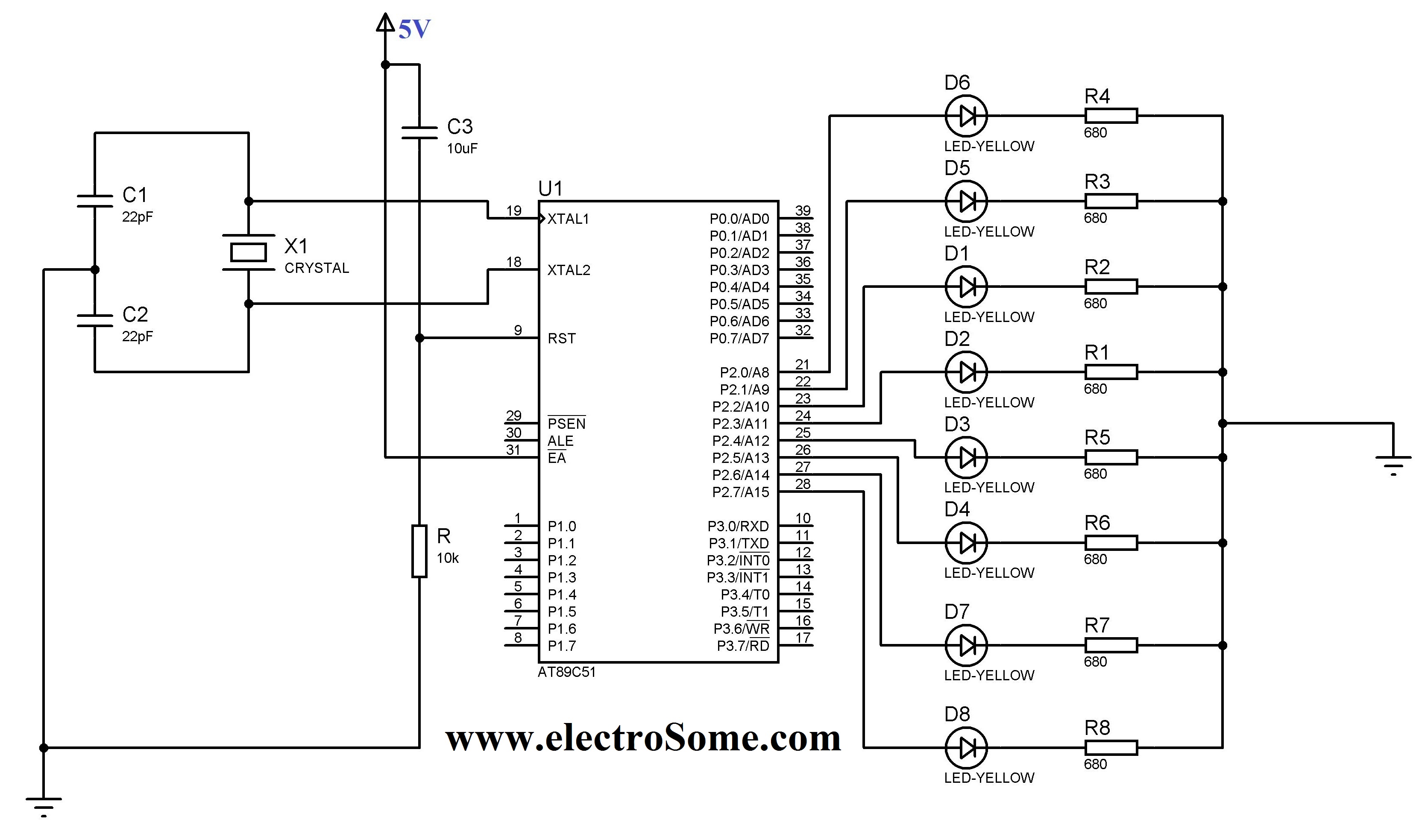
The 8051 controller is mask-programmable, meaning it is programmed during manufacturing and cannot be reprogrammed afterward. However, the AT89C51 microcontroller, a derivative of the 8051, is reprogrammable. This device includes a timer, a serial port interface, and interrupt control,...
This 555 timer circuit toggles a relay when a button is pressed. Pins 2 and 6, the threshold and trigger inputs, are held at half the supply voltage by two 10K resistors. When the output is high, the capacitor...
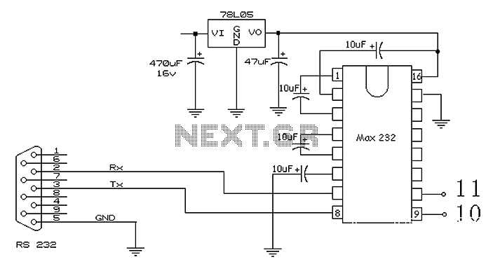
The 51 microcontroller features a full-duplex serial communication port, enabling straightforward serial communication between the microcontroller and a computer. However, certain conditions must be met for effective communication, such as the computer's serial port operating at RS232 levels while...
A stepper motor controller is required to operate a stepper motor, as a stepper motor cannot function merely by connecting it to a power supply. A stepper motor controller is an essential component for the effective operation of stepper...
A very simple controller circuit with impressive performance. If a fully automatic computer-controlled rotator is not affordable but enhanced capability is desired from a basic rotator, the ZL1BPU Rotator Controller offers a simple "point and shoot" computer-controlled antenna solution....
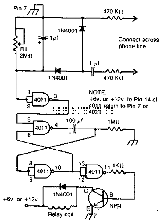
By cross-connecting the telephone ringing circuit, when the phone rings, the circuit activates the relay. It utilizes a delay in contact to drive various devices such as bells, sirens, buzzers, or lights. The telephone ringing circuit is designed to detect...
Warning: include(partials/cookie-banner.php): Failed to open stream: Permission denied in /var/www/html/nextgr/view-circuit.php on line 713
Warning: include(): Failed opening 'partials/cookie-banner.php' for inclusion (include_path='.:/usr/share/php') in /var/www/html/nextgr/view-circuit.php on line 713