
Yaesu G-400 Antenna Rotator Controller
The ZL1BPU Rotator Controller circuit design integrates several key components to ensure reliable operation and user-friendly functionality. The microcontroller serves as the central processing unit, executing the command set and managing communication with the PC. The 5V voltage regulator is crucial for supplying stable power to the microcontroller and associated components, ensuring consistent performance. The RS232 interface allows for seamless communication with the PC, enabling the user to send commands effectively.
The relay drive transistors are essential for controlling the rotator's movement. By interlocking with the existing LEFT and RIGHT switches, these relays prevent simultaneous activation, which could lead to damage. This design consideration enhances the robustness of the controller and ensures that it operates safely within the parameters of the existing rotator hardware.
The use of hysteresis in the control algorithm significantly improves the system's stability. By implementing a window comparator technique, the controller minimizes oscillations around the desired heading, which can occur due to minor fluctuations in feedback signals. This feature is particularly beneficial in applications where precision is critical, such as in VHF and UHF communications.
Overall, the ZL1BPU Rotator Controller represents a cost-effective solution for enhancing the capabilities of existing rotator systems. Its design allows for easy integration, minimal modifications to existing hardware, and compatibility with a wide range of rotators, making it an attractive option for amateur radio operators looking to upgrade their equipment without incurring high costs.A very simple controller circuit, with fairly smart performance! Can`t afford a fully automatic computer controlled rotator, but would like more capability from your basic rotator Would you like a simple to use "point and shoot" computer controlled antenna You`ve come to the right place! The ZL1BPU Rotator Controller has been designed as an add-on unit for the popular Kenpro KR-400 and Yaesu G-400 rotators. The controller consists of a small circuit board which fits inside the rotator control box (see picture). With this unit the rotator gains automatic heading seeking, computer control, and even heading control by clicking on a map or selecting a country prefix!
The ZL1BPU Rotator Controller should work with any rotator with AC motor drive and a 500 Ohm feedback pot, such as the CDR CD-44 and the HY-GAIN HAM IV. It will also operate with both North-centred and South-centred rotators, as only the PC software setting changes.
Computer rotator controllers tend to be expensive - however you can build this one for under $50! The firmware supplied supports a rich specialized command set and also responds to SARTEC, ORION and YAESU commands, making it compatable with most popular multi-function logging and digital mode programs that feature rotor control. The controller could also form the basis of a self-contained replacement controller, for rotators with faulty or missing controllers.
Just add the power supply circuitry shown in the G-400/KR-400 Rotator Schematic - all you really need is a 24V AC supply, a 6V DC supply, and a 70 - 100 uF AC motor capacitor. The small circuit board can be fitted inside the rotator control box, and operates from the controller`s power supply.
No holes need be made in the box, and all modifications are internal and reversible if the need arises. There are only five wires between the unit and the existing rotator box. The serial (PC) control cable can sneak out the back panel through an existing hole. The suggested circuit board is single sided, 60mm x 60mm (without the relays), and can be etched or engraved.
See the picture to the right, which is larger than life-sized. The board contains an inexpensive micro controller, a 5V voltage regulator, a simple transistor RS232 interface, and two relay drive transistors to activate the rotator. The relays are interlocked with the existing LEFT and RIGHT switches, so there is no possibility of motor or controller damage.
The unit is given heading commands via the PC serial port, from a special program, a digital modes or logging program with rotator control, or a simple terminal program. The commands are in the form of hexadecimal or decimal numbers, depending on the protocol, and the controller in effect "pushes the buttons" on the associated rotator control box until the requested heading is reached.
This means that it will go to the correct heading without the need for a button to be held down to keep the rotator moving. It also allows for sophisticated computer applications to control the rotator. Accuracy is limited mostly by the host rotator and control unit. Typically 2 ° to 3 ° heading resolution and about ±5 ° positioning accuracy. The smallest command that will cause movement is about 5 °. A heading approached from clockwise may differ from the same heading approached from anticlockwise by ±5 °.
Hardly a problem with HF beamwidths of 30 ° or more, but not appropriate for some VHF and UHF terrestrial and satellite systems. The Rotator Controller uses hysteresis through the use of a window comparator technique, to prevent hunting and poor stability, which results in the heading uncertainty specified.
The hysteresis could be re 🔗 External reference
Related Circuits
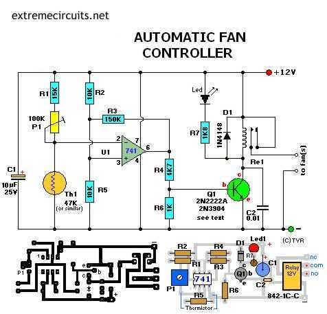
Transistor Q1 can be a 2N2222(A), 2N3904, NTE123A, ECG123A, etc. Not critical at all. It acts only as a switch for the relay so almost any type will work, as long as it can provide the current needed to...
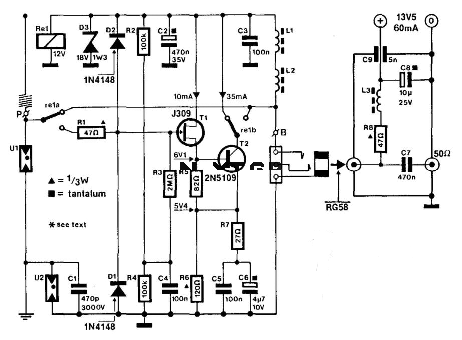
A J309 Siliconix FET is utilized to drive a 2N5109 in a wideband RF amplifier setup. A relay is incorporated to bypass the amplifier in transmit mode, if required. An active antenna element is a 2-meter 5/8-wave whip. The...
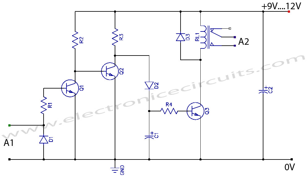
VCR Camera Video Detector Switch Controller Circuit. This video detector switch controller circuit utilizes the video output from a VCR or camera to... This circuit functions as a video detector switch controller, designed to manage the video output from a...
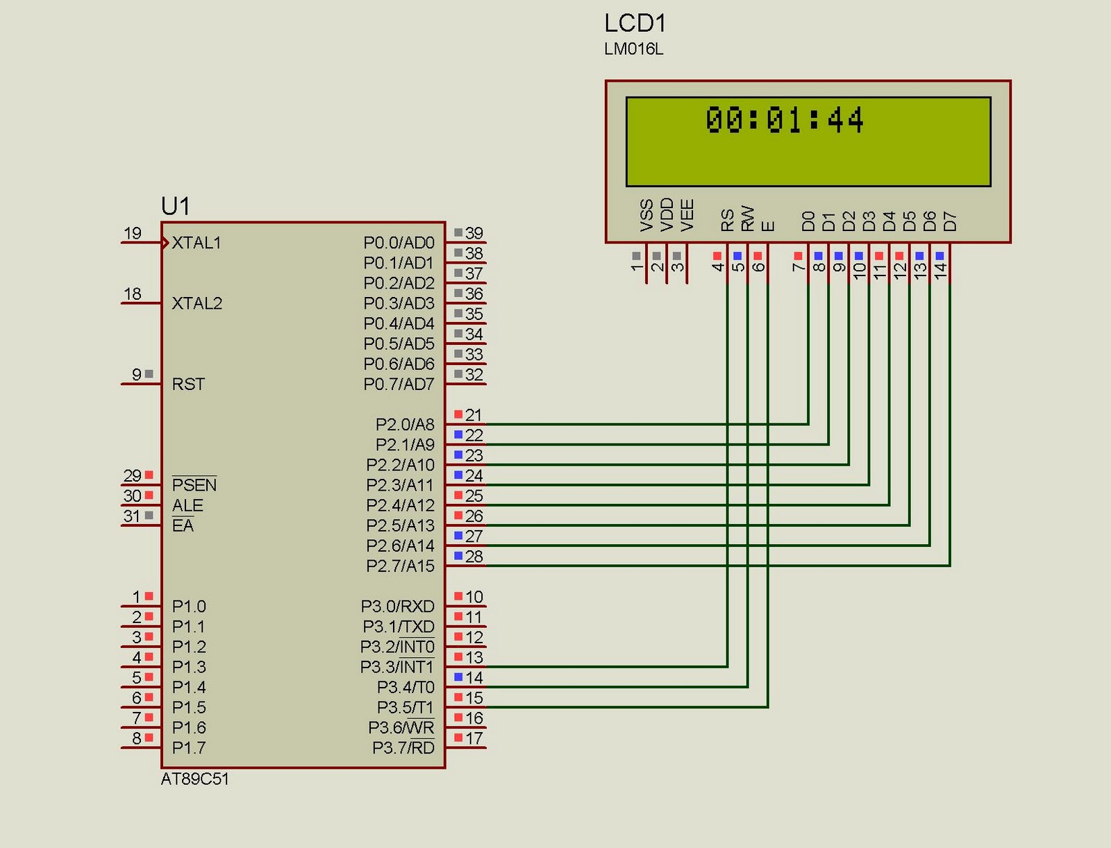
This project implements a real-time clock using the 89C51 microcontroller. The clock's data format is hours:minutes:seconds, which is displayed on a 16x2 LCD. The code has been tested and compiled using the Keil uVision compiler. The circuit diagram for...
This new loop antenna designed by Graham Maynard features a six-foot square, six-turn loop that is aperiodic in nature, covering a frequency range of 50 KHz to 5000 KHz. Its size allows for inconspicuous mounting against a garden fence,...
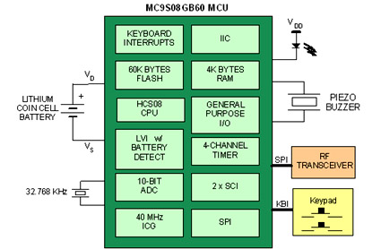
Battery-powered devices, such as electric toothbrushes, shavers, cell phones, PDAs, MP3 players, and remote controls, are integral to daily life. Consequently, power management has become a critical consideration for embedded designers. Microcontrollers (MCUs) provide various methods for managing power...