
Logic Power Control circuit diagram for 78xx Regulator
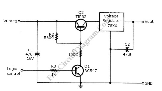
The described circuit employs a logic-level control mechanism for managing the output of a linear voltage regulator, specifically the 78xx series, which is widely utilized for providing stable voltage outputs in various electronic applications. The circuit is designed to enable or disable the power supply to the load based on a digital control signal, thereby allowing for efficient power management.
In this configuration, a transistor acts as a switch that is controlled by a digital signal from a microcontroller or other digital logic device. When the control signal is high (logic 1), the transistor is turned on, allowing current to flow through the 78xx regulator, which in turn supplies power to the connected load. Conversely, when the control signal is low (logic 0), the transistor is turned off, interrupting the current flow and effectively shutting down the power to the load.
The use of TTL or CMOS logic levels ensures compatibility with a wide range of digital circuits. The transistor is typically an N-channel MOSFET or an NPN bipolar junction transistor, chosen for its low on-resistance and fast switching characteristics. The 78xx series regulator is selected according to the desired output voltage and current requirements, with common options including 7805 for +5V, 7812 for +12V, and 7809 for +9V outputs.
Additional components may include pull-down resistors to ensure the transistor remains off when the control signal is not asserted, as well as decoupling capacitors to stabilize the output voltage and reduce noise. The overall design promotes energy efficiency by allowing the power supply to be turned off when not needed, thereby minimizing power consumption in battery-operated or energy-sensitive applications.
This logic power control circuit is particularly advantageous in scenarios where digital control is essential, such as in EEPROM programming, where precise power management is critical to prevent data corruption during programming cycles.Logic power control of analog regulator can be useful in application where a digital circuit/controller need to control power source, such as in EEPROM programmer or other power controls. This is a circuit provide ON-OFF control for 78xx regulator using digital (TTL or CMOS) signal level.
This circuit uses transistors in series with the 78XX regulator, which.. 🔗 External reference
Related Circuits
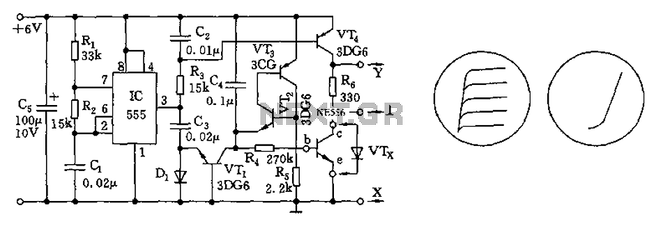
The transistor characteristic curve tracer circuit depicted in Figure 555 illustrates the characteristics of a transistor. It utilizes two voltages: a step wave applied to the base (b) to generate different base currents (Ib), and a sawtooth waveform at...
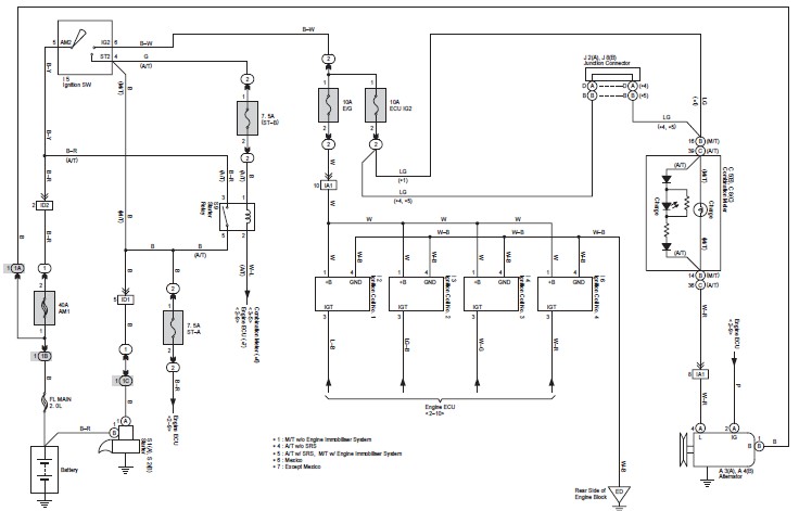
This document contains the complete wiring diagram for the Toyota Avanza. It is highly useful for technicians and car owners during service or maintenance activities. The wiring diagram includes the wiring for the Front Wiper and Washer, Headlight, ABS,...
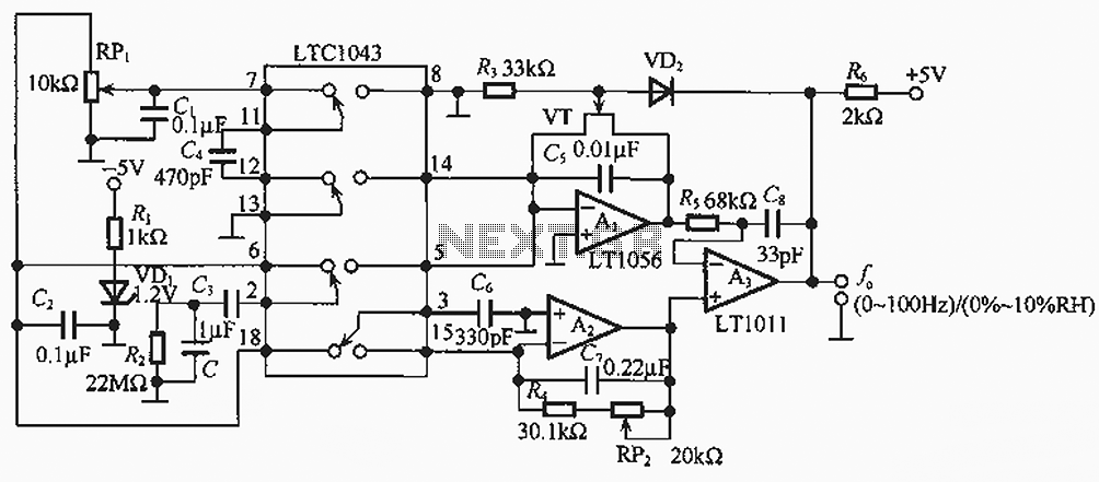
The humidity/frequency conversion circuit operates similarly to the previously mentioned humidity sensors. At a humidity level of 76%, the equivalent capacitance is 500 pF, with a capacitive relative humidity variation rate of +1.7 pF/%. The circuit includes an integrating...
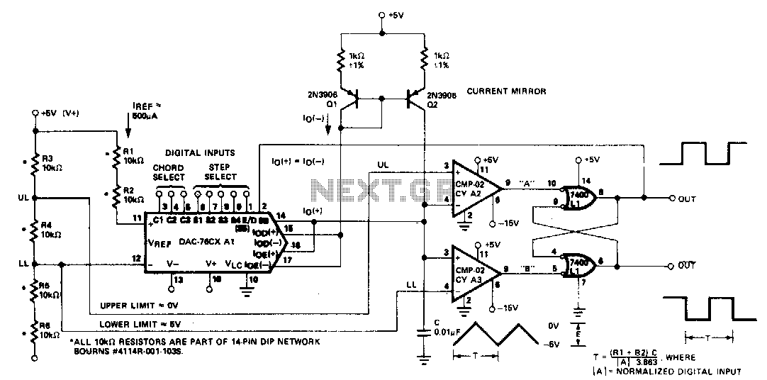
The microprocessor-controlled oscillator has a frequency range of 8159 to 1, covering from 2 Hz to 20 kHz. An exponential, current output integrated circuit digital-to-analog converter (DAC) functions as a programmable current source, alternately charging and discharging a capacitor...
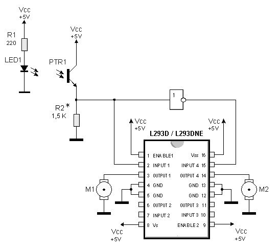
By utilizing logic chips, the behavior of a robot can be enhanced, allowing for the implementation of more complex algorithms. Logic chips, also known as logic gates or digital logic integrated circuits, are fundamental components in digital electronics that perform...
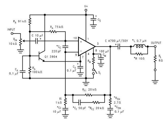
The LM2876 audio power amplifier circuit can be designed as a simple, high-efficiency power audio amplifier capable of delivering 40W of continuous average power to an 8-ohm load with a total harmonic distortion plus noise (THD+N) of 0.1% from...
Warning: include(partials/cookie-banner.php): Failed to open stream: Permission denied in /var/www/html/nextgr/view-circuit.php on line 713
Warning: include(): Failed opening 'partials/cookie-banner.php' for inclusion (include_path='.:/usr/share/php') in /var/www/html/nextgr/view-circuit.php on line 713