
Toyota Avanza Wiring Diagram
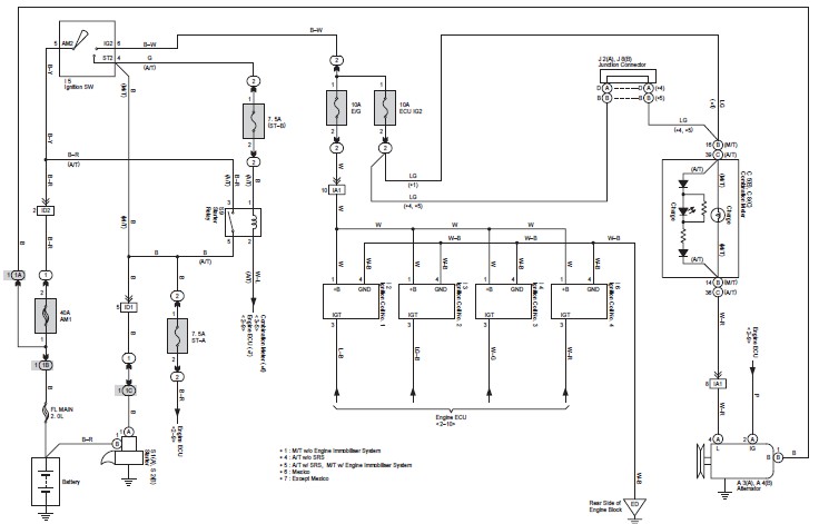
The Toyota Avanza wiring diagram serves as a crucial reference for understanding the electrical layout and connections within the vehicle. It provides detailed illustrations that depict the wiring pathways for various components, ensuring efficient troubleshooting and repair processes.
The diagram includes sections for essential systems such as the Front Wiper and Washer, which outlines the motor connections, switch configurations, and fuse locations, enabling technicians to diagnose issues related to wiper functionality effectively. The Headlight wiring section details the connections for both low and high beam circuits, including relay placements and bulb specifications, which are vital for ensuring optimal lighting performance.
Furthermore, the Anti-lock Braking System (ABS) wiring diagram illustrates the connections between the wheel speed sensors, control module, and power supply, which is essential for maintaining vehicle safety and performance. The Air conditioning system wiring details the compressor connections, control switches, and relay configurations, facilitating effective maintenance of the vehicle's climate control system.
Overall, this comprehensive wiring diagram is an indispensable tool for both technicians and car owners, providing the necessary information to ensure proper service and maintenance of the Toyota Avanza's electrical systems.This is the complete Toyota Avanza wiring diagram document. Its very useful for technician and car owner during service or maintanance activity. The wiring diagram documents contain the wiring of Front Wiper and Washer, Headlight, ABS, Air.. 🔗 External reference
Related Circuits
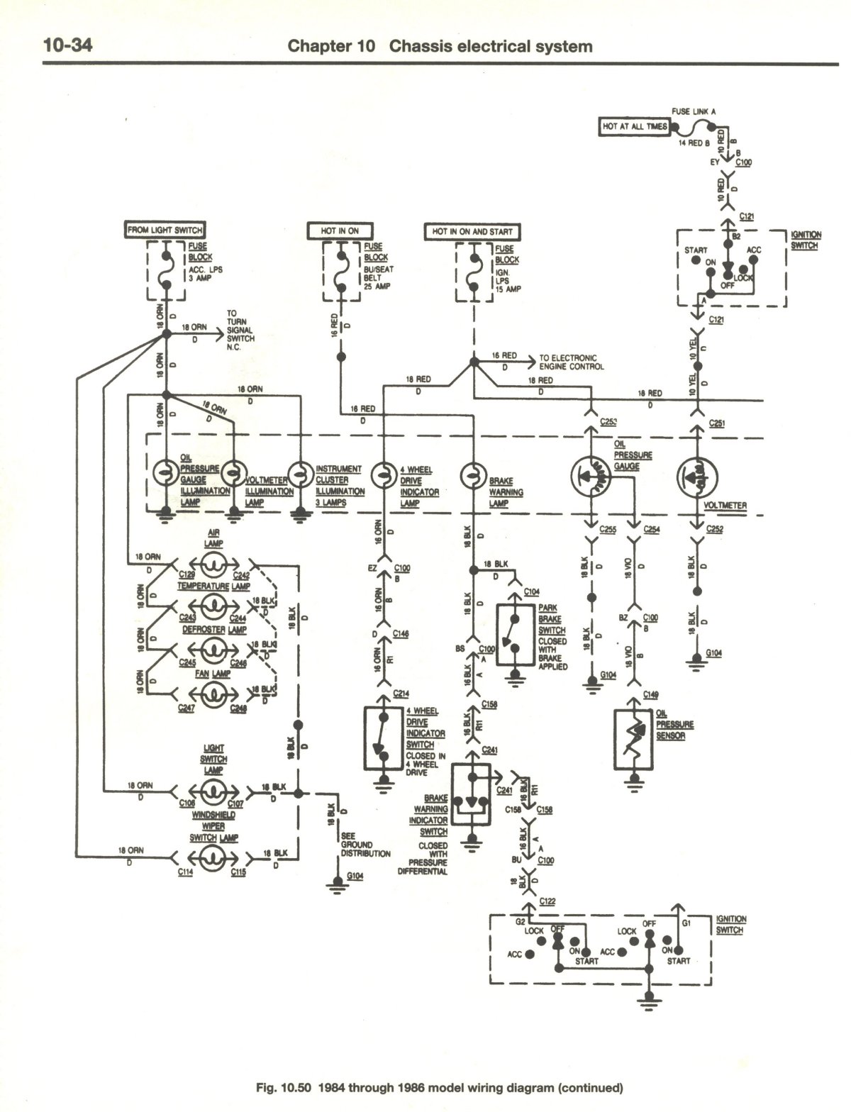
If there is no output at terminal 66 RED, it indicates a potential issue. The dash light dimmer may be set to the "OFF" position, or there could be significant corrosion on the wiper of the rheostat, preventing proper...
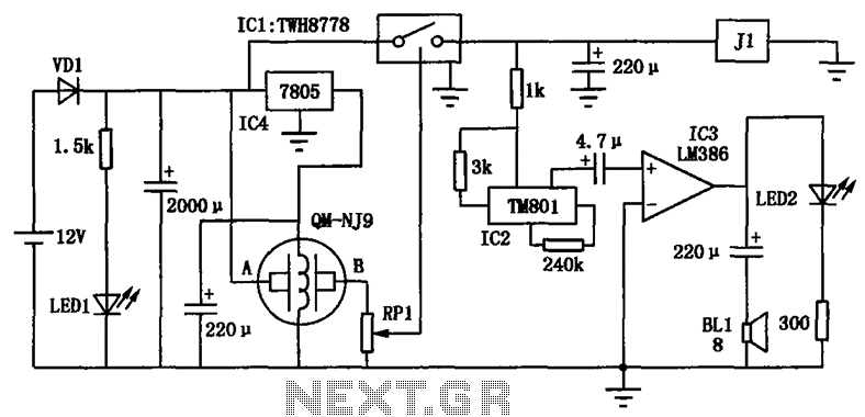
The alcohol detection alarm controller circuit is illustrated in the figure. It utilizes the QM-NJ9 alcohol gas sensor, which detects the presence of alcohol vapors. When alcohol is detected, the resistance between the AB-QM-NJ9 decreases, causing the wiper of...
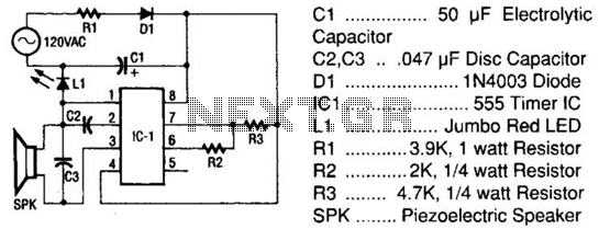
The tester comprises a rectifier circuit and a multivibrator circuit. The alternating current (AC) voltage is half-wave rectified by diode D1 and stored in capacitor C1. Resistor R1 is employed to limit the current through D1 to a safe...
A schematic arrangement for a two-quadrant controller is shown in the figure below. This figure illustrates the outer speed control loop and the inner current control loop. The tachogenerator derives the speed feedback signal; alternatively, an approximation of the...
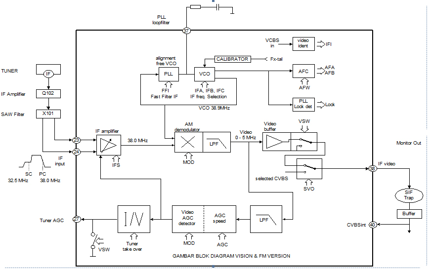
This section is designed to amplify the signal until it reaches the required level. The IF amplifier is equipped with an Automatic Gain Controller (AGC) that regulates the amplification to ensure a constant amplitude output for the video. The...
This is a very simple FM receiver built using only one transistor. It does not utilize any chips or other active components. The output is connected to earphones; an amplifier circuit is required if the radio is to be...