
Logic Probe
The described logic probe functions as a diagnostic tool for digital circuits, utilizing a single CMOS integrated circuit (IC) to indicate the state of the logic levels present at its input. The probe is capable of displaying three distinct logic conditions: High, Low, and Pulsing. These states are visually represented through the use of LEDs, which illuminate based on the voltage level detected at the probe's input.
In the high state, the probe detects a voltage level that is above a certain threshold, typically around 2.5V for CMOS technology, and the corresponding LED will light up to indicate this condition. Conversely, when the input is in the low state, which is generally below 0.8V, another LED will illuminate to signal this logic condition. The pulsing state occurs when the input is transitioning between high and low states, indicating that the circuit is actively switching, which is crucial for debugging timing issues in digital circuits.
An important feature of this logic probe is its ability to handle the high impedance state of tri-output logic ICs. When the probe is connected to an output that is neither driven high nor low (i.e., in a high impedance state), the LEDs remain off. This prevents false readings and ensures that the probe only indicates valid logic levels.
The power supply for the logic probe is sourced directly from the logic circuit under test, allowing for flexible operation across a range of voltages from 3V to 15V. This capability makes the probe versatile for testing various CMOS logic families, accommodating different logic levels without the need for an external power supply. The design, therefore, enhances the usability of the probe in various electronic applications, making it an essential tool for engineers and technicians involved in digital circuit design and troubleshooting.This logic probe uses a single CMOS IC and shows three logic conditions, High, Low and Pulsing. In addition if the probe input is neither hi or low (the high impedance state of tri-output logic ic`s) then no LED`s will light. Power from the logic probe is taken from the logic circuit under test; using a CMOS IC enables logic circuits to be tested using voltages from 3 to 15 volts.
🔗 External reference
Related Circuits
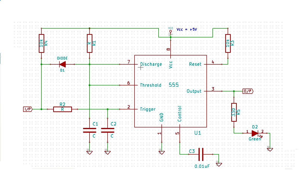
Create a 555 timer-based circuit where the output pin of the 555 timer is held low by default when powered on, and the input pin is held high at power on. The main requirement is that the output pin...
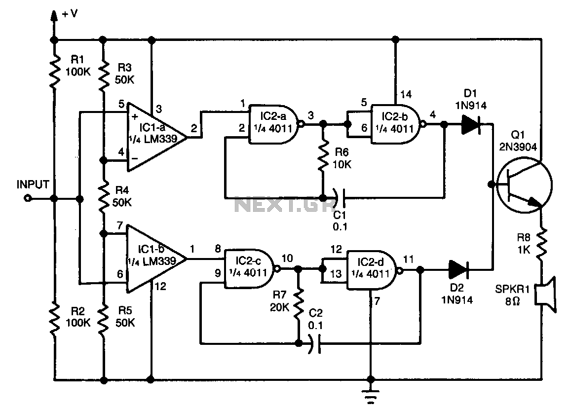
This tester provides an audible indication of the logic level of the signal presented to its input. A logic high is indicated by a high tone, a logic low is indicated by a low tone, and oscillation is indicated...
Figure 1 illustrates an AND gate logic circuit with the logic expression P=A. Figure B depicts two photodiodes connected in series. When the input logic levels A=1 and B=1, the output P=1. Similarly, this configuration can be used to...
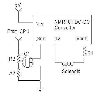
Despite exhaustive searching, every reasonably priced solenoid valve for controlling propane during pushbutton start required 12VDC, beyond the capabilities of a normal pump battery. There are methods to generate HV pulses which will actuate the solenoid, which will remain...
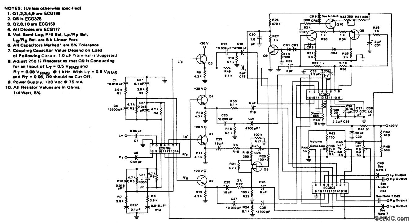
4-channel SQ logic decoder with a current drain of 75 mA at 20 volts. The input impedance is 2M ohms, and the output impedance is 2K ohms (courtesy of GTE Sylvania Incorporated). The 4-channel SQ logic decoder is an integrated...
This circuit is so sensitive it will detect mains hum. Simply move it across any wall and it will detect where the mains cable is located. It has a gain of about 200 x 200 x 200 = 6,000,000...