
Logic Probe for Tri-state Logics
The Logic Probe circuit for tri-state logic is designed to detect and indicate the state of digital signals in a circuit that can exist in three different states: high, low, and high-impedance (or tri-state). This is particularly useful for troubleshooting digital circuits where multiple devices may share a common bus.
The basic components of a Logic Probe circuit typically include a microcontroller or logic gates, resistors, diodes, and LEDs for visual indication. The circuit operates by applying the input signal to a comparator, which determines the voltage level of the signal. If the signal is high (logic 1), the corresponding LED will illuminate, indicating a high state. Conversely, if the signal is low (logic 0), another LED will light up to indicate a low state. In the case of a high-impedance state, the circuit will not activate either LED, allowing the user to identify the tri-state condition.
Power supply considerations must also be addressed, as the circuit usually requires a stable voltage source, typically between 5V to 15V, depending on the logic levels being monitored. The design can be compact, often implemented on a small printed circuit board (PCB) to facilitate portability and ease of use.
Additionally, protective components such as current-limiting resistors and clamping diodes may be included to prevent damage to the circuit from over-voltage conditions. The Logic Probe can be an invaluable tool in debugging and validating the functionality of digital systems, providing clear visual feedback on the state of the signals being monitored.This is a simple circuit of Logic Probe for Tri-state Logics. This circuit can be built only in a few hours. Besides that, this circuit has some other. 🔗 External reference
Related Circuits
Ideally, any testing equipment will not draw any current from the device under test. This ideal condition can be approximated by designing a testing device. To achieve the ideal condition where testing equipment does not draw current from the device...
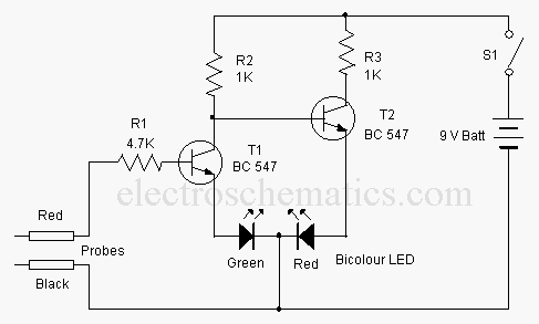
This is a basic logic state indicator designed to test whether the output of a digital integrated circuit (IC) is in a logic high (1) or logic low (0). The bicolor LED illuminates green when the logic state is...
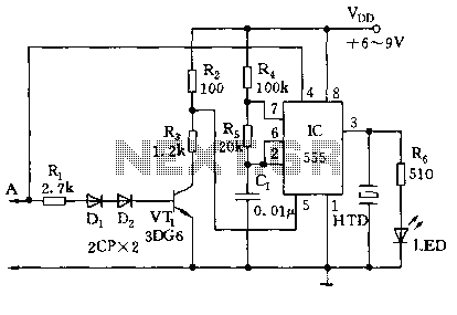
The circuit utilizes a 555 timer along with resistors R4, R5, and capacitor C1 configured in a controllable multivibrator mode. This setup forces the reset terminal (pin 4) to a specific state, allowing for control of the external logic...
Logic power control of an analog regulator can be useful in applications where a digital circuit or controller needs to manage a power source, such as in EEPROM. In electronic systems, managing power effectively is crucial for the performance and...
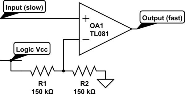
Invert a signal to drive FETs with rapid rise and fall times. It was suggested to use an inverter (not a chip) instead of logic chips, which are designed to be either fully ON or OFF. The individual has...
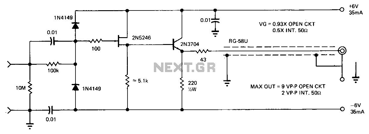
This FET probe features an input impedance of 10 MΩ, which is shunted by 8 pF. Removing the protective diodes reduces this impedance to approximately 4 pF. The frequency response of the probe ranges from DC to 20 MHz...